Visualizing Sine Wave with Mechanical Movements #algorithmic #mechanical #fabrication #p5js #javascript #itp #introduction-to-fabrication #fabricating-mechanical-automatons
I have been making and posting daily creative coding experiments (on my Instagram) for almost 2 years now. One of the mathematical functions that keep coming back is a sine function (such as in the sketch below, which utilizes a combination of sine and cosine functions). As I have been studying fabrication techniques and mechanical movements recently, I had this idea of creating an automaton that visualizes a sine wave.
 |
|---|
| Sketch on on August 3, 2023 |
| [ View post on Instagram ] |
One of the mechanisms that I recently learned is called cam, which is commonly used to transform rotary motion into linear motion. I tried imagining and sketching what a cam would look like if the linear movement it produces follows a sine wave. I started with a regular sine wave, and tried to wrap it around a circle. While it gave me a general idea of what it might look like, it was far from accurate.
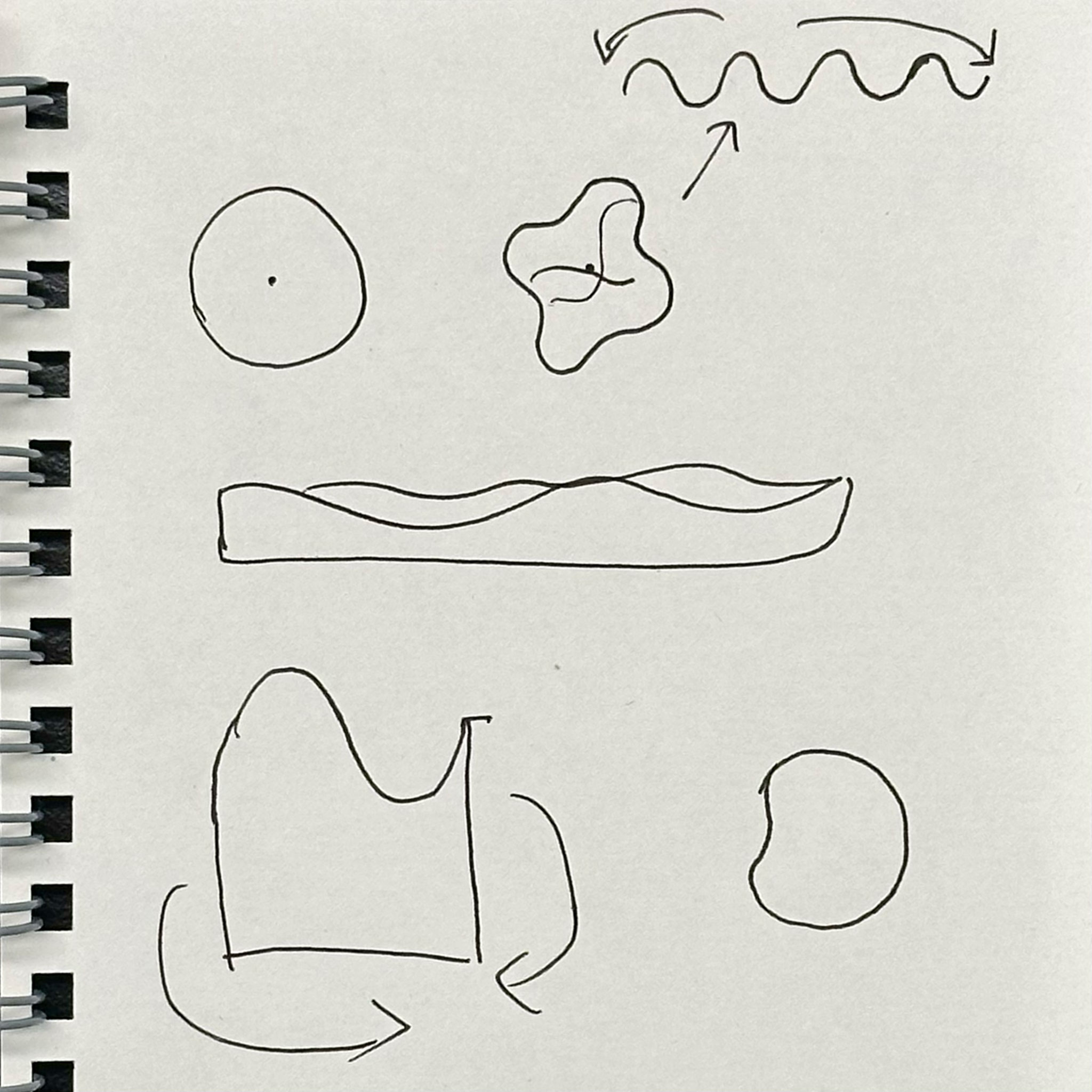
Luckily, I have created similar shapes with code before, so I was able to quickly sketch out a much more accurate contour in p5.js.
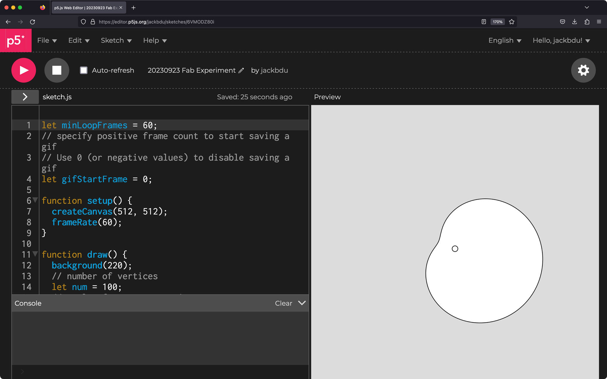
I started with just a cam, and then added a vertical shalf and its trace to better illustrate this movement.
I also tried cams whose own full rotation produces multiple cycles of a sine wave.
 |
 |
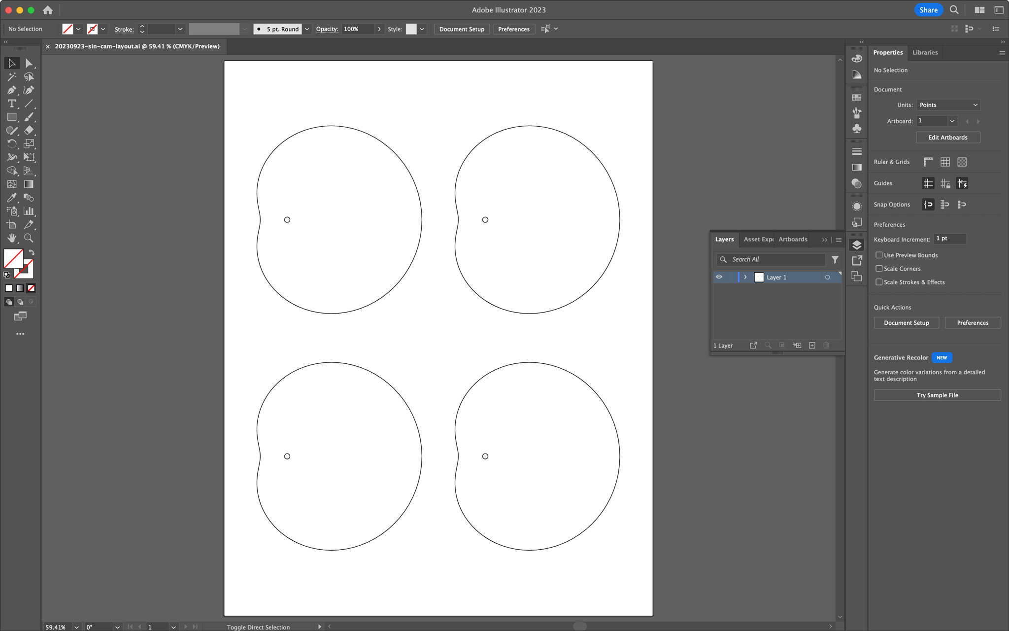
I think these ones are going to be helpful when I need to combine sine waves of different frequencies. For now, the first one, which has the smallest dimple, should be the easiest to fabricate and also most likely to create least amount of frication when interacting with a shalf. Hence, I exported a high resolution picture of that cam so that I could adjust it to my desired dimensions in Adobe Illustrator before it was sent to print.
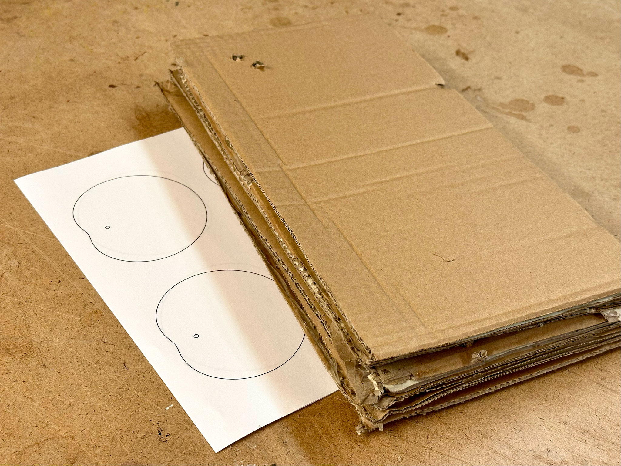
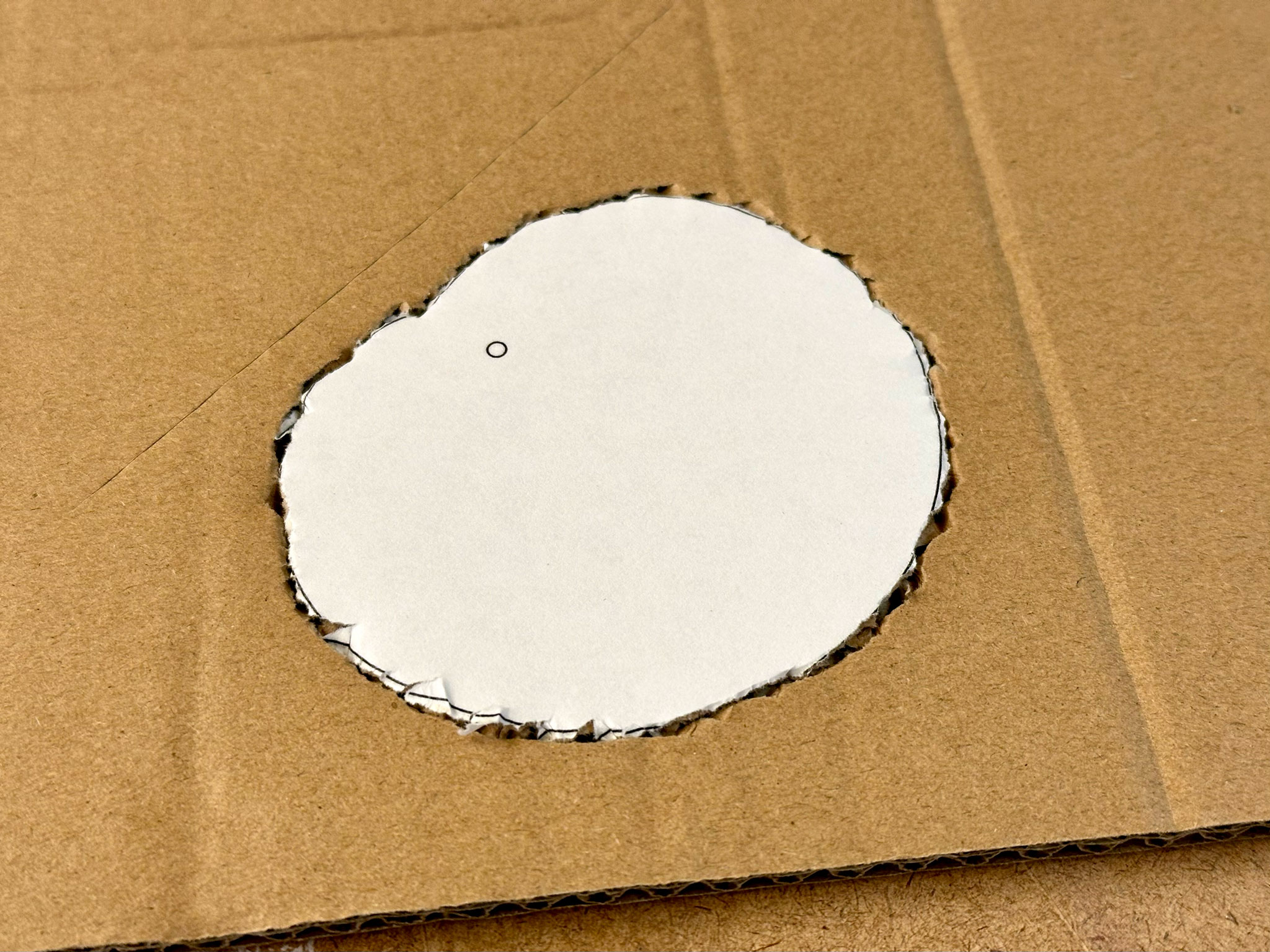
With the printed reference in hand, I started to work on a cardboard prototype. I found a large thick cardboard box, which ended up being my sole cardboard source.
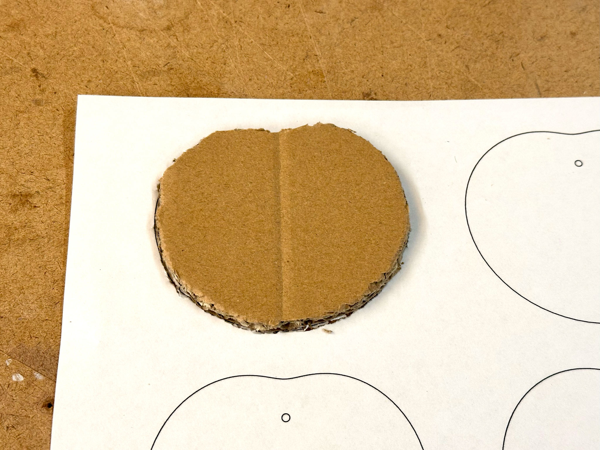
For the first few cam pieces, I started by scoring the outline with a small flat-head screwdriver, then cut and trimmed the piece with a utility knife until it was as close to the reference as possible.
 |
 |
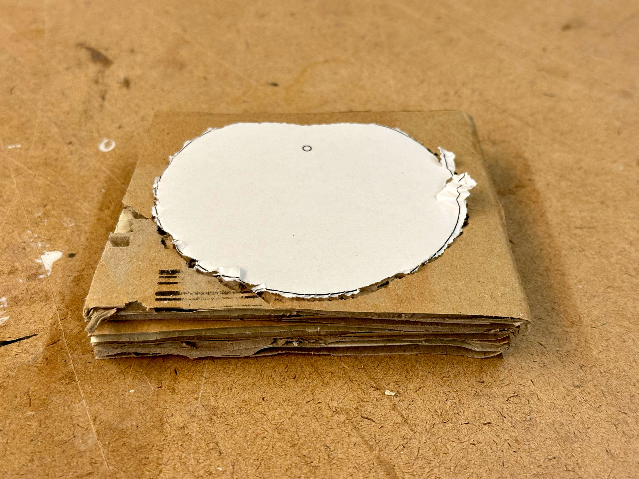
Very quickly, I became impatient and started stacking and cutting multiple pieces of cardboard at the same time.
 |
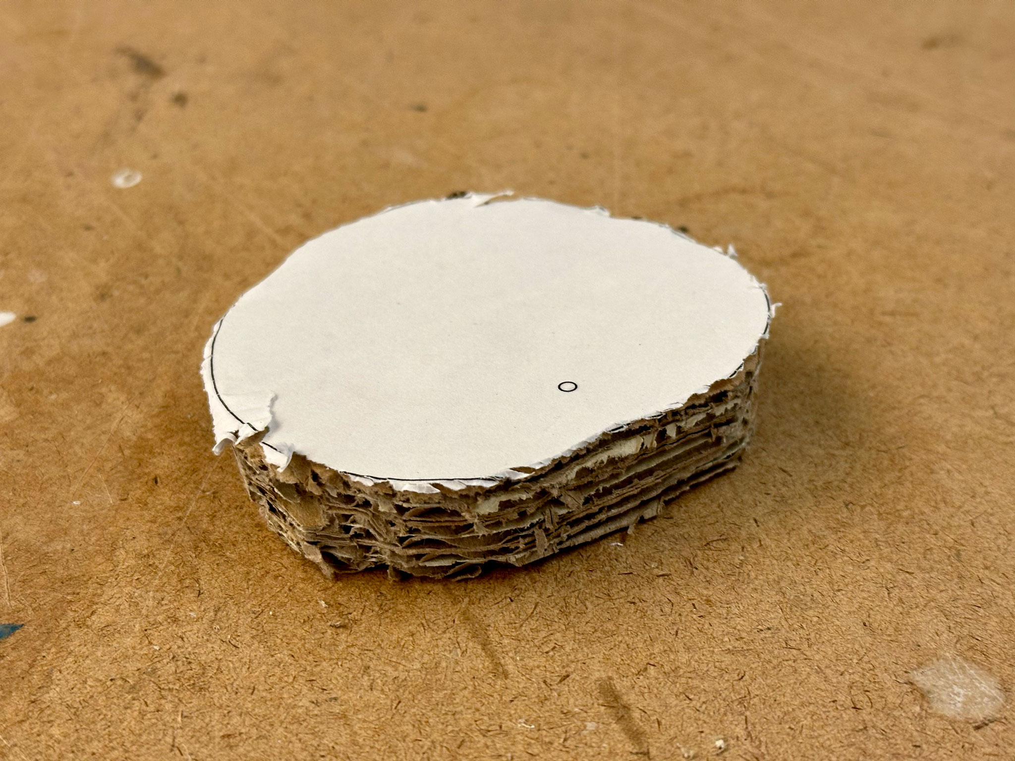 |
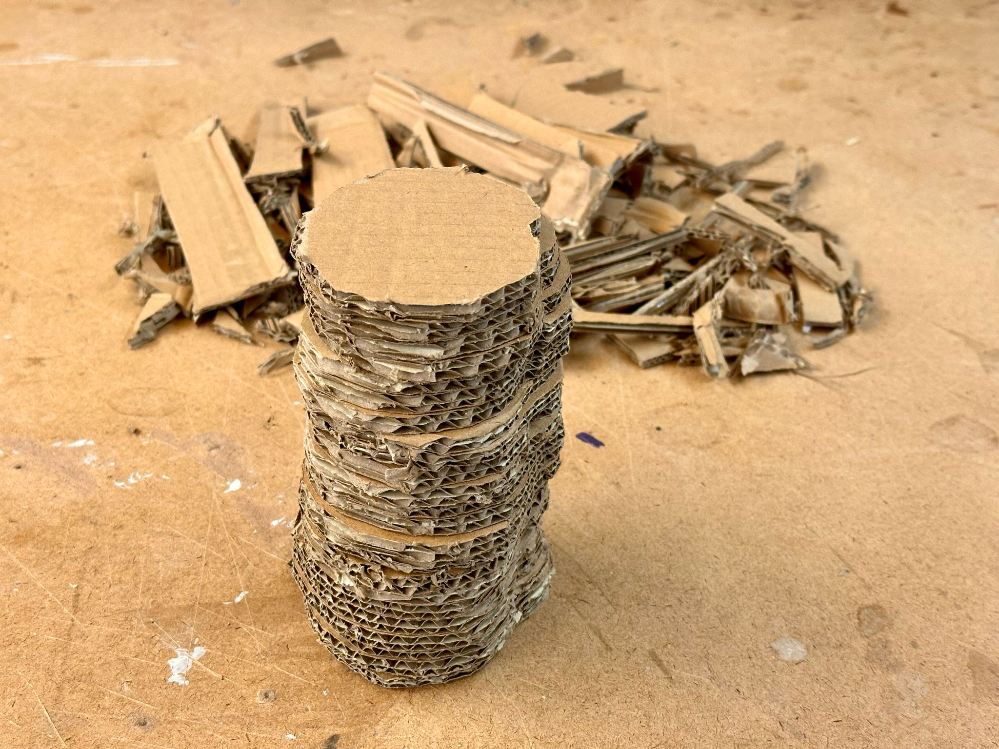
That really helped speed up the process. I was able to make about 23 cams in a relatively short period of time, even though I did have to go back and trim some of them a bit more so that the sides are as even as they could be.
The next step was to look for a rod (Yes, I did not have a rod. I sort of went with it without much planning). Tres, who just finished his automaton prototype, was kind enogh to lend me one of his wooden rod, and I also picked up another broken one that he persumably disposed of. Since we were discouraged to use any power tool, I manually made holes for all of the cams with a drill bit.
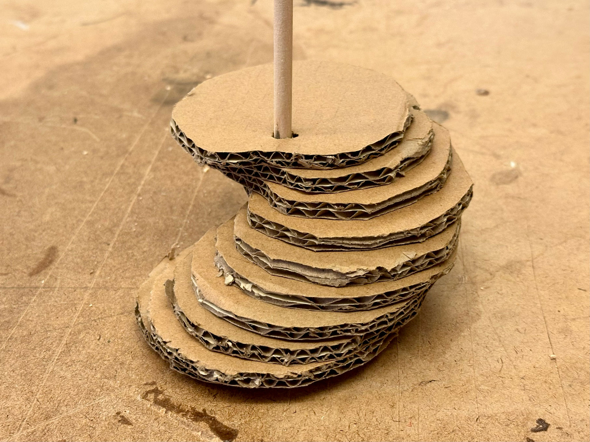
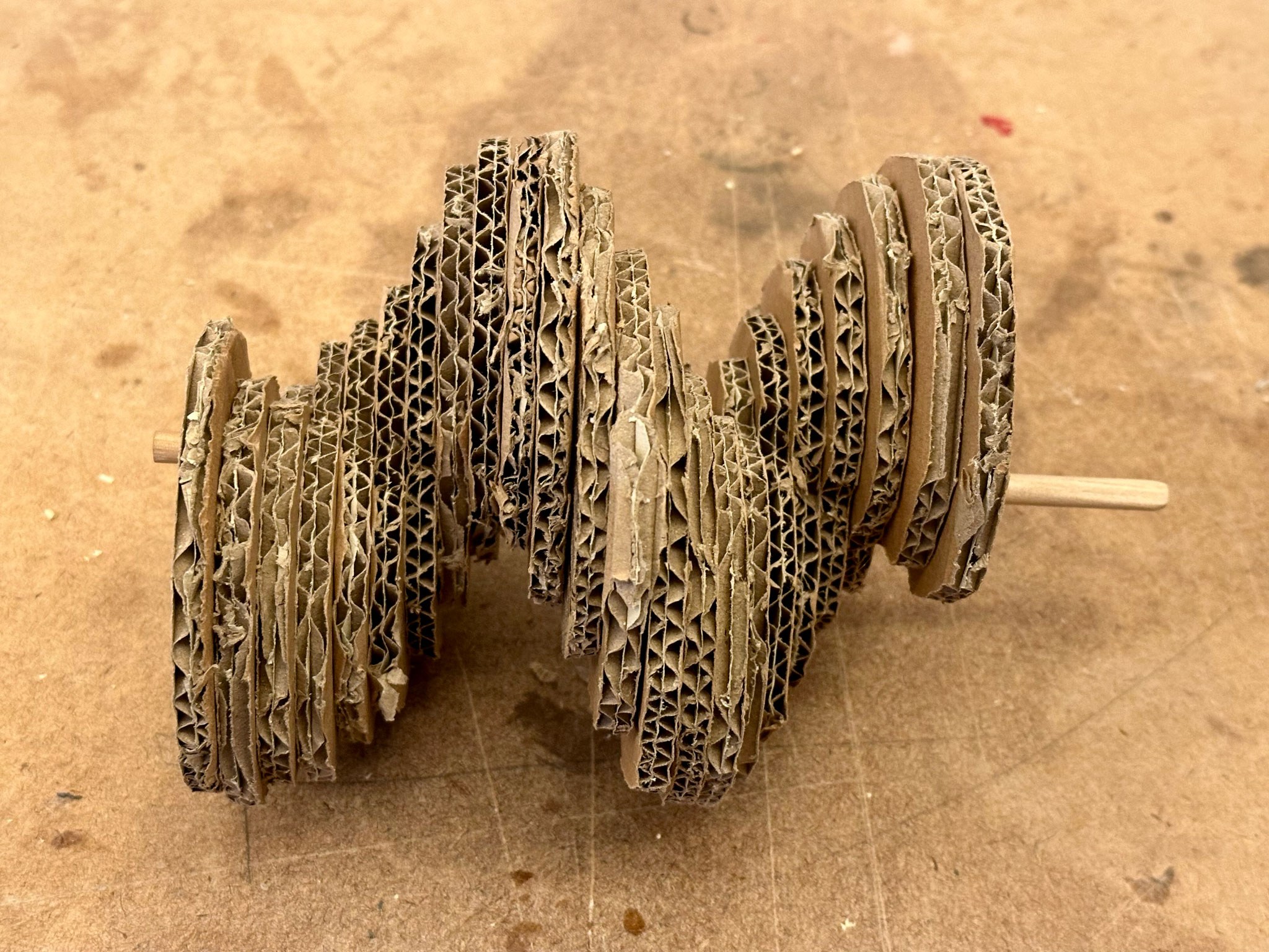
Looking good! Time to hot glue them together! I found the gluing process very satisfying, maybe it was because I have not worked on a physical piece for a very long time. It also felt so special to see this repetitive pattern coming together physically, as I have only experimented with repetition in digital forms.
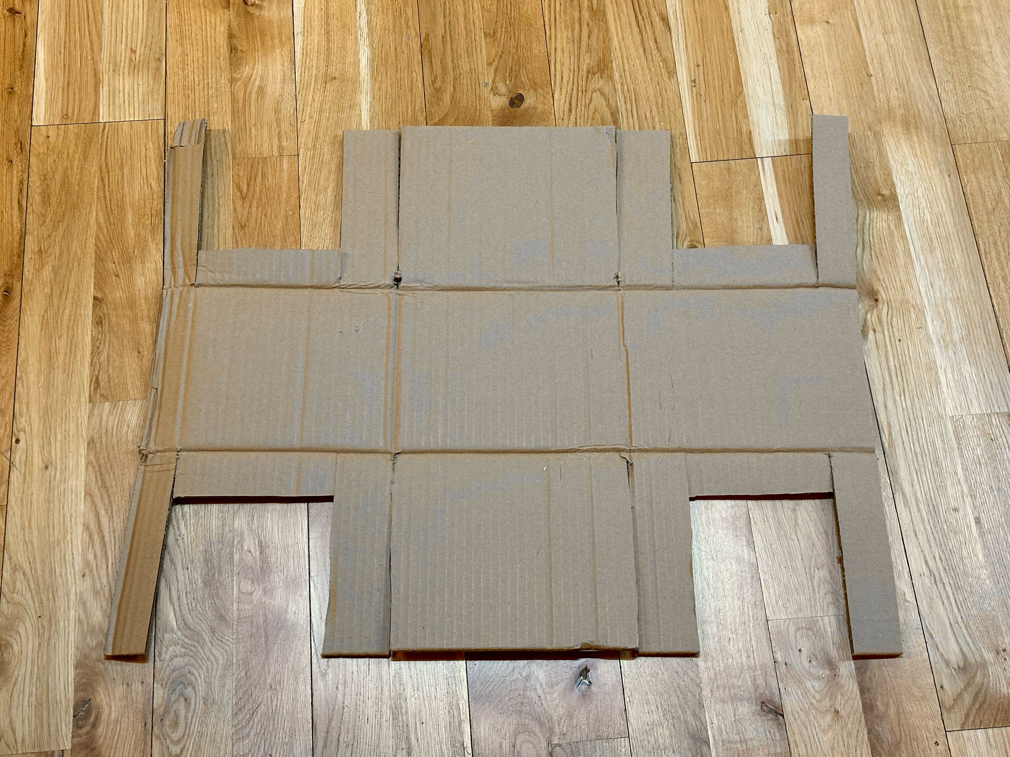
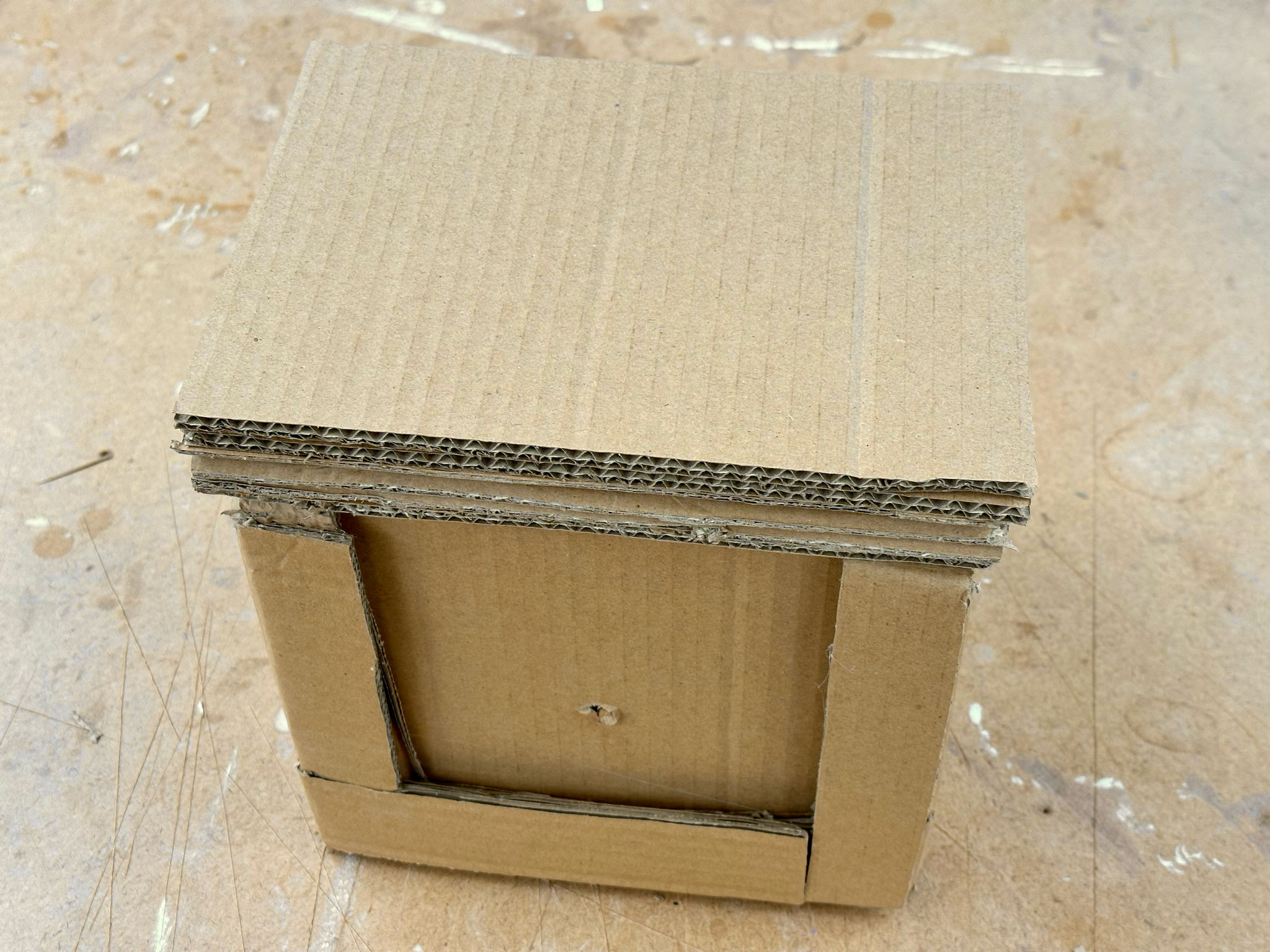
At this point, I needed build a structure to hold the rod. It was such a coincident that the unused portion of the cardboard box seemed to serve as a perfect base. I did some rough measurements and cut it into a shape that could be folded into a half-opening box.
After being fully assembled, it seemed to rotate pretty well. The cams alone were already creating a very interesting motion as they were rotated.
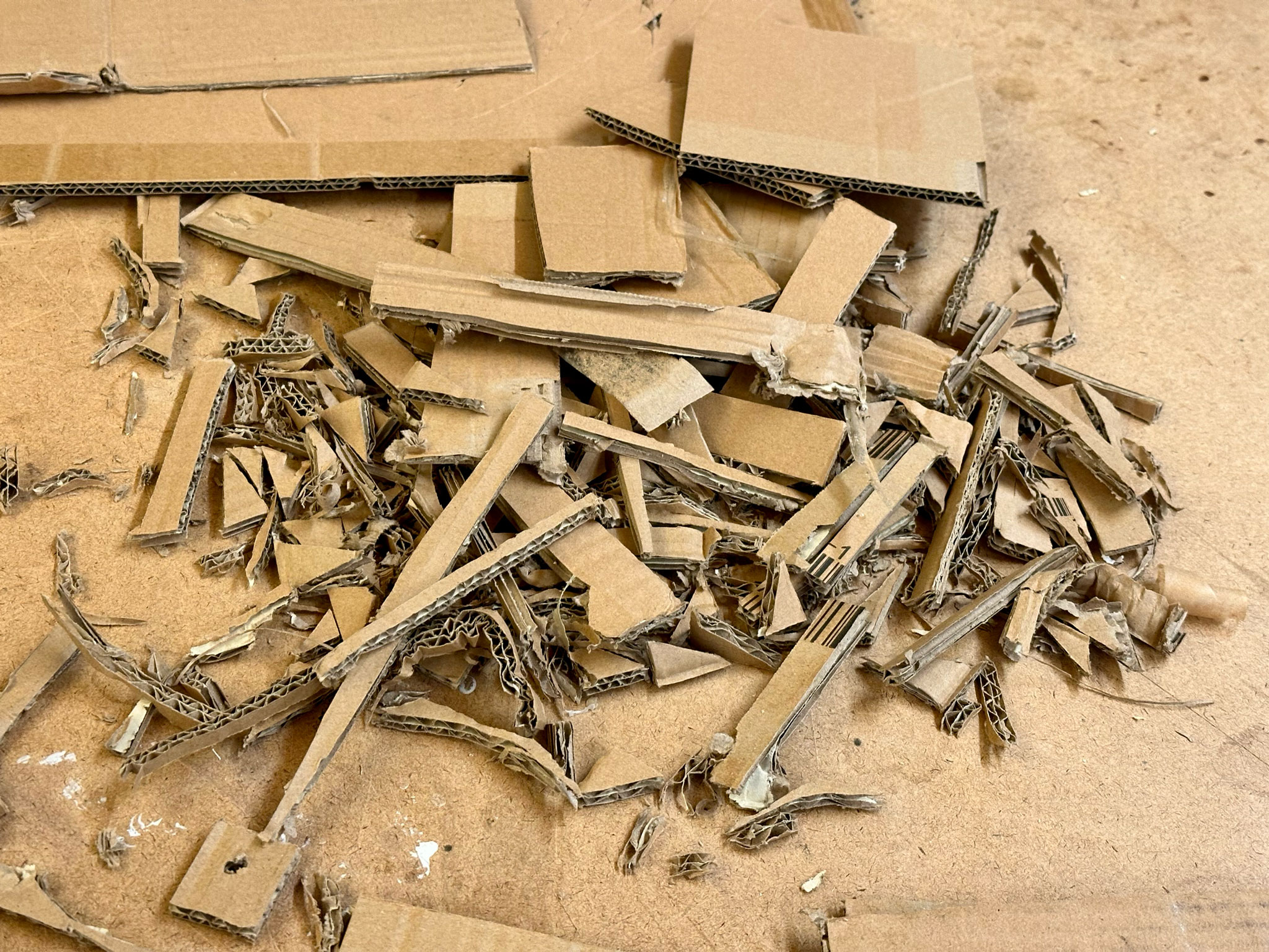
As a bonus, here are the scrap pieces that had been accumulating.
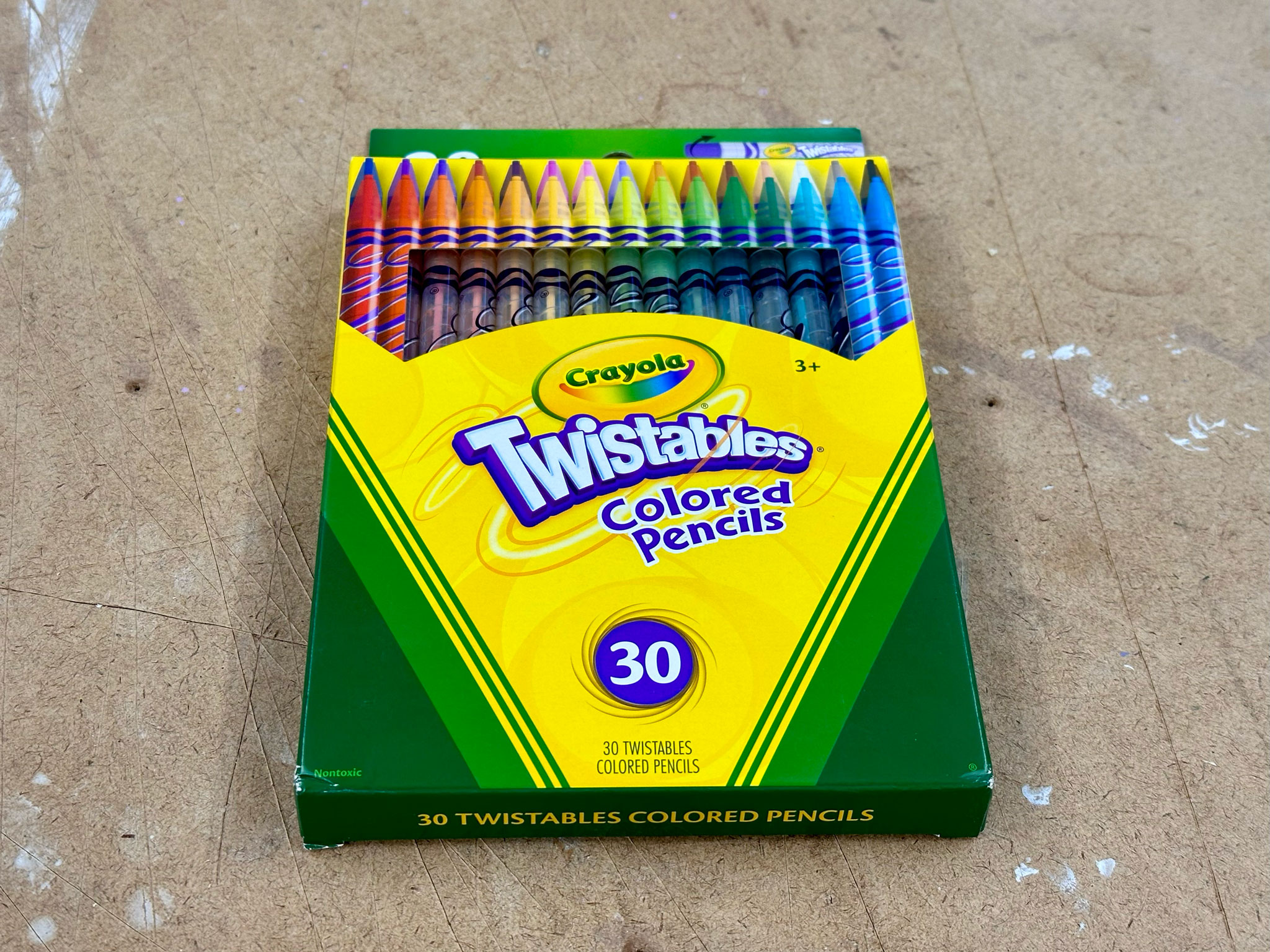
Finally, I needed to figure out what should go on top of the cams. My immediate thought was to have multiple short rods, which I did not have. I considered many different materials that I could find either at ITP or at NYU MakerSpace right across the street, but none of them worked. Despite it was a rainy day, I eventually decided to go to Target, the closest department store, and I found some Twistables colored pencils. They are smooth throughout, at just about the right length, and they are colorful. All seemed to be good characteristics for my prototype.
After fighting with the rain and the wind, these pencils safely arrived at ITP.
I was so excited to try them out! I made a thick cardboard block and drilled holes to hold the pencils in place. It was impossible get it to work. The holes were either too tight for the pencils to move freely, or too loose for the pencils to stay straight. I had to switch to a wood block, hoping it would work better.
 |
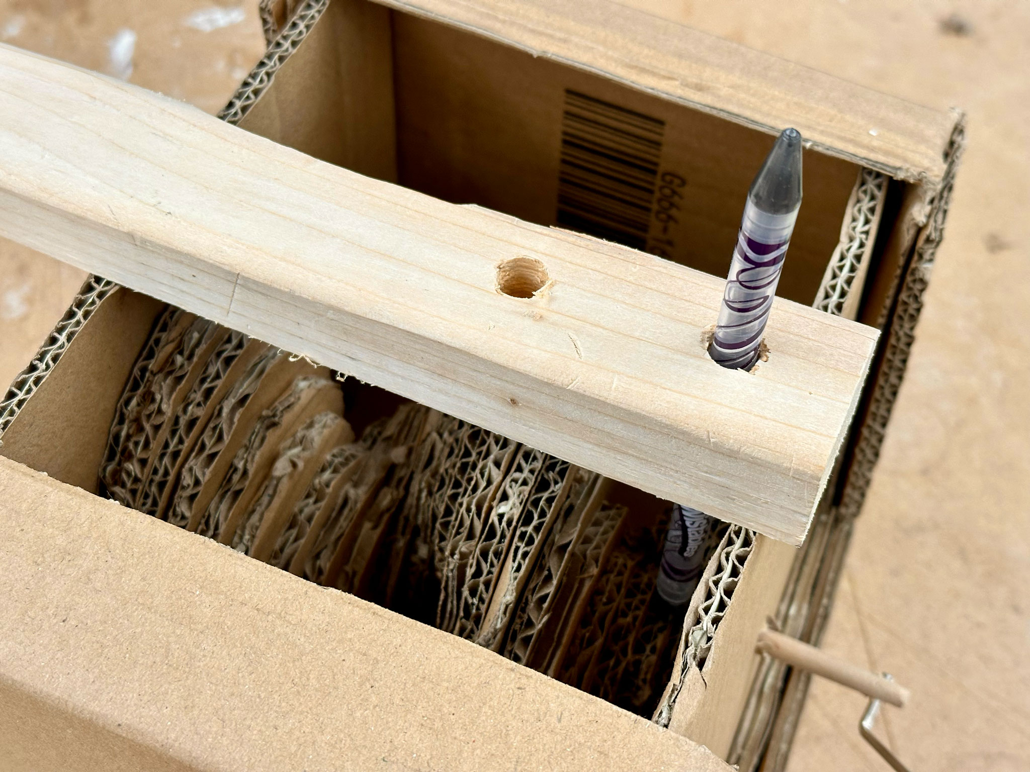 |
The wood block definitely worked better, but with the amount of frication between the cardboard cams and the pencil, the mechanism kept getting stuck. My classmate, Josh, suggested that I should try increasing the touching surface. I did that by hot-gluing an extra piece of cardboard at the bottom of the pencil and it worked!
 |
|---|
| Me taking a video while holding the prototype and rotating the shalf, trying not to bother other people |
While the motion was far from perfect, this (mostly) cardboard prototype proved that my idea could work. It also convinced me that a wooden prototype would work much more reliably.
The topic of the most recent fabrication class was repeatability. I took this opportunity to create multiple wooden cams that were shaped exactly the same.
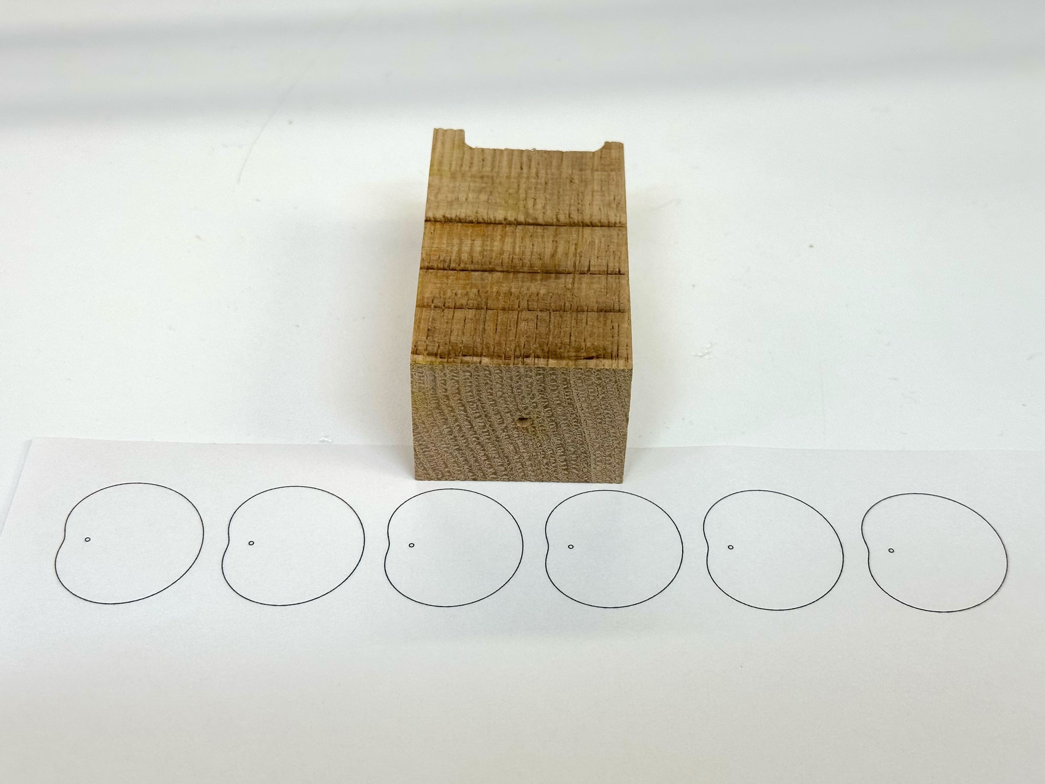
I picked the largest block of scrap wood that I could find and resized the template to fit the wood block.
 |
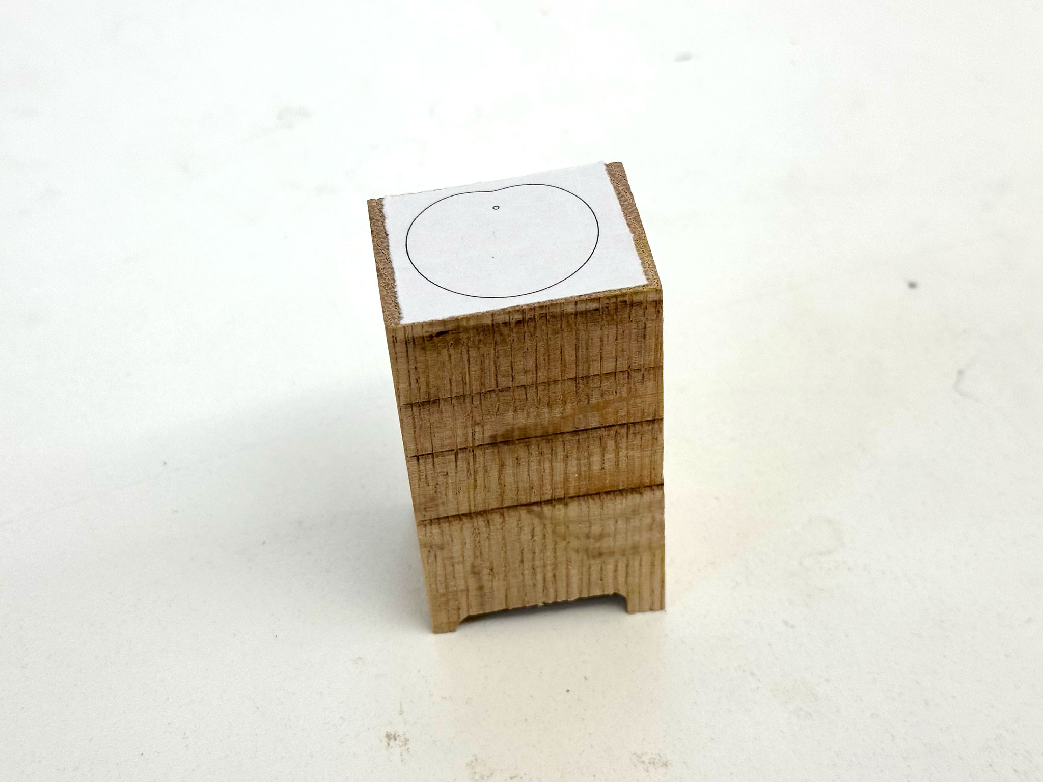 |
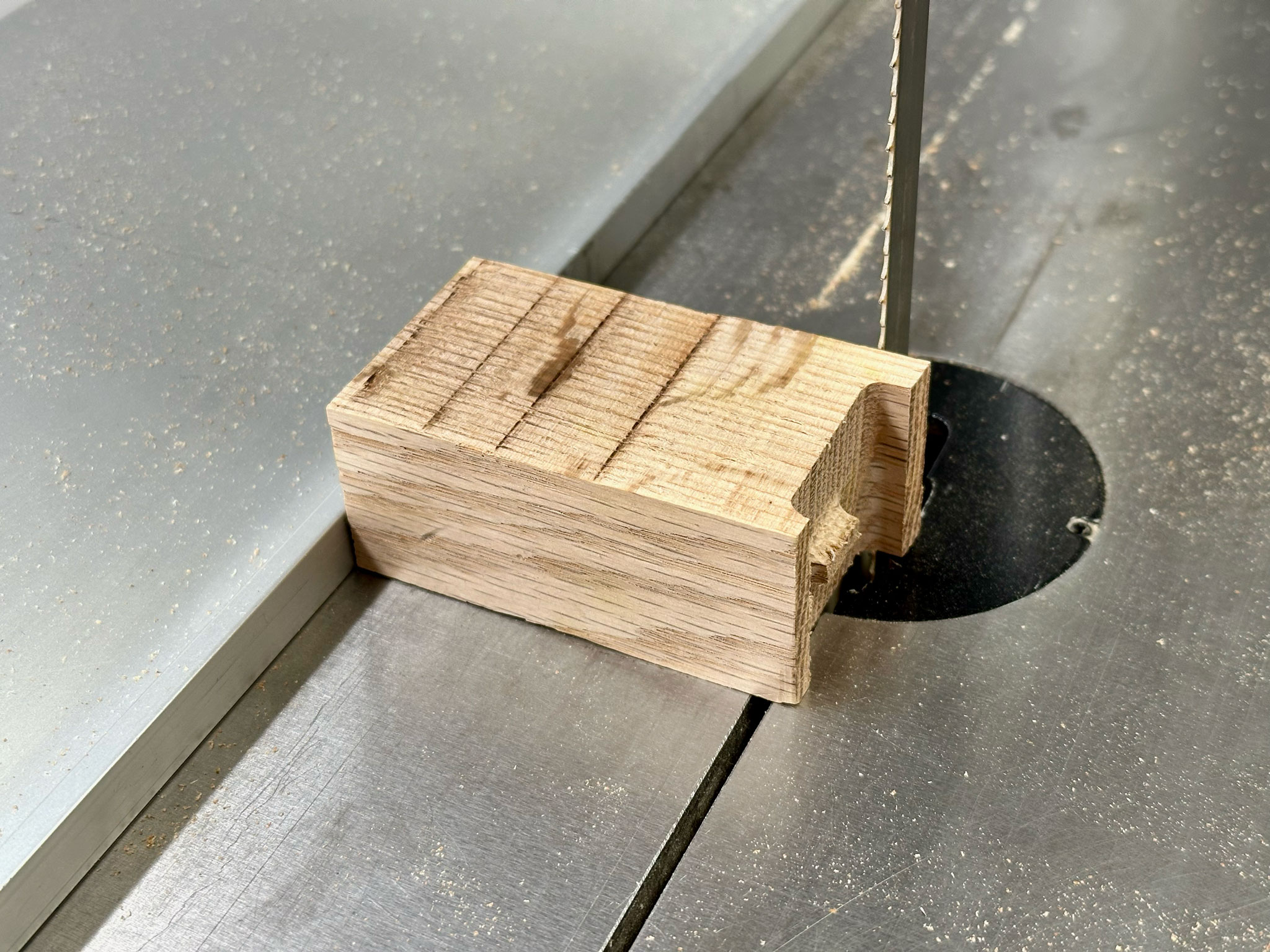
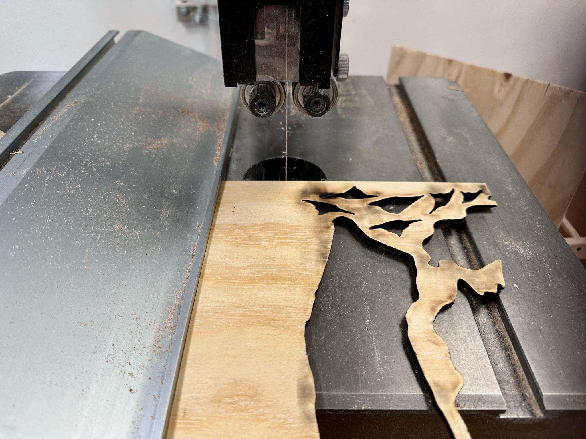
I started off my trimming off the irregullar side of this block on the band saw, so it was flat and square all on sides.
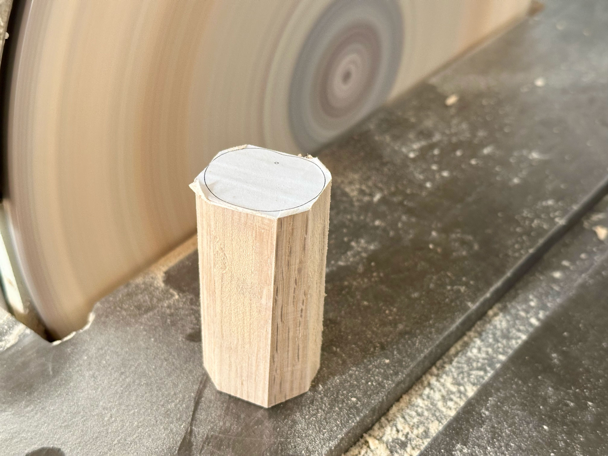
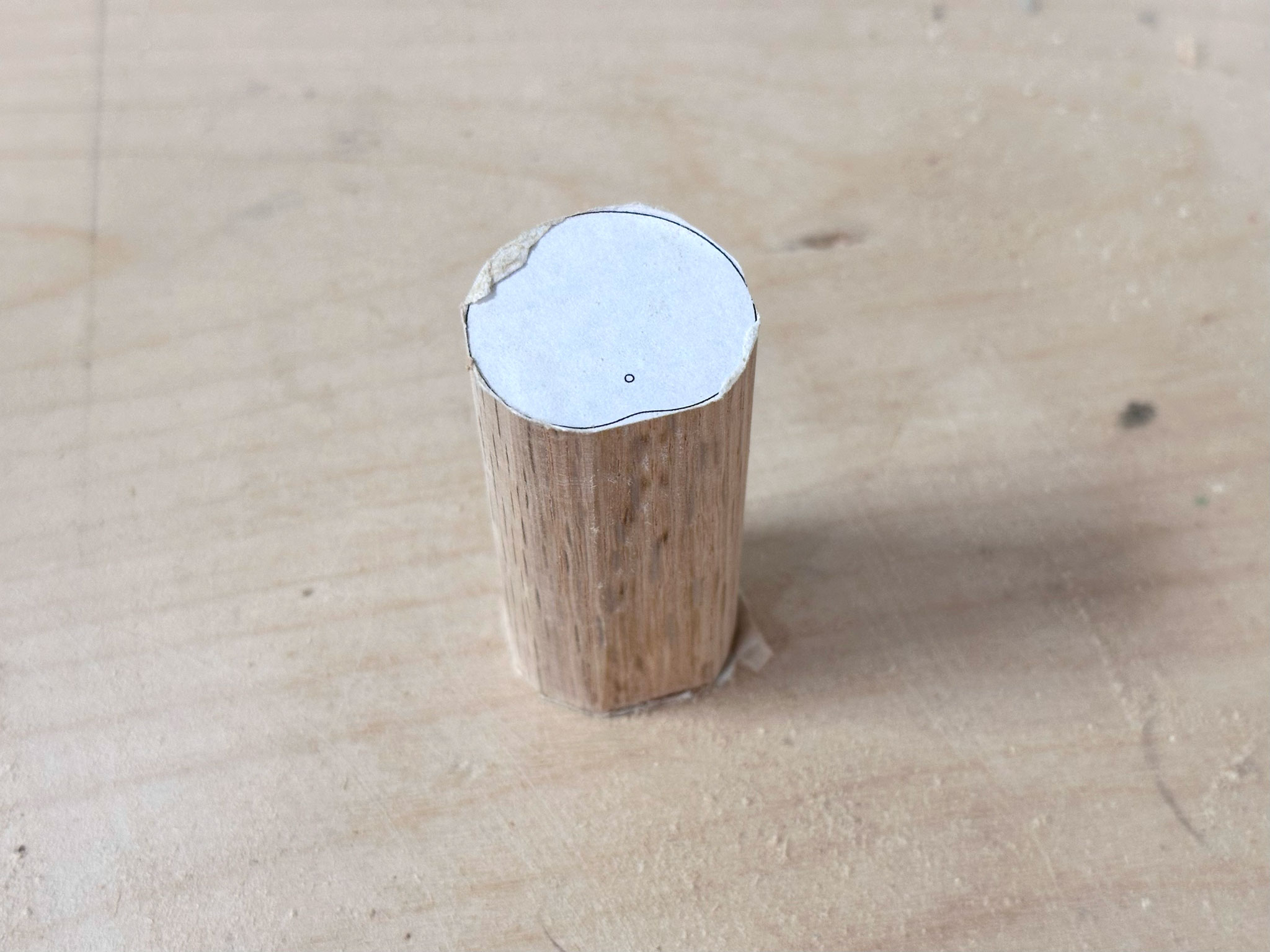
Then I moved to the disk sander to sand off the edges and carefully shape it based on the template. During this process, I found it very hard to keep the piece completely straight. I beleive it takes both practice and techniques. Next time, I would probably stick templates on both sides, and maybe also use the band saw to cut reference points across the block.
 |
 |
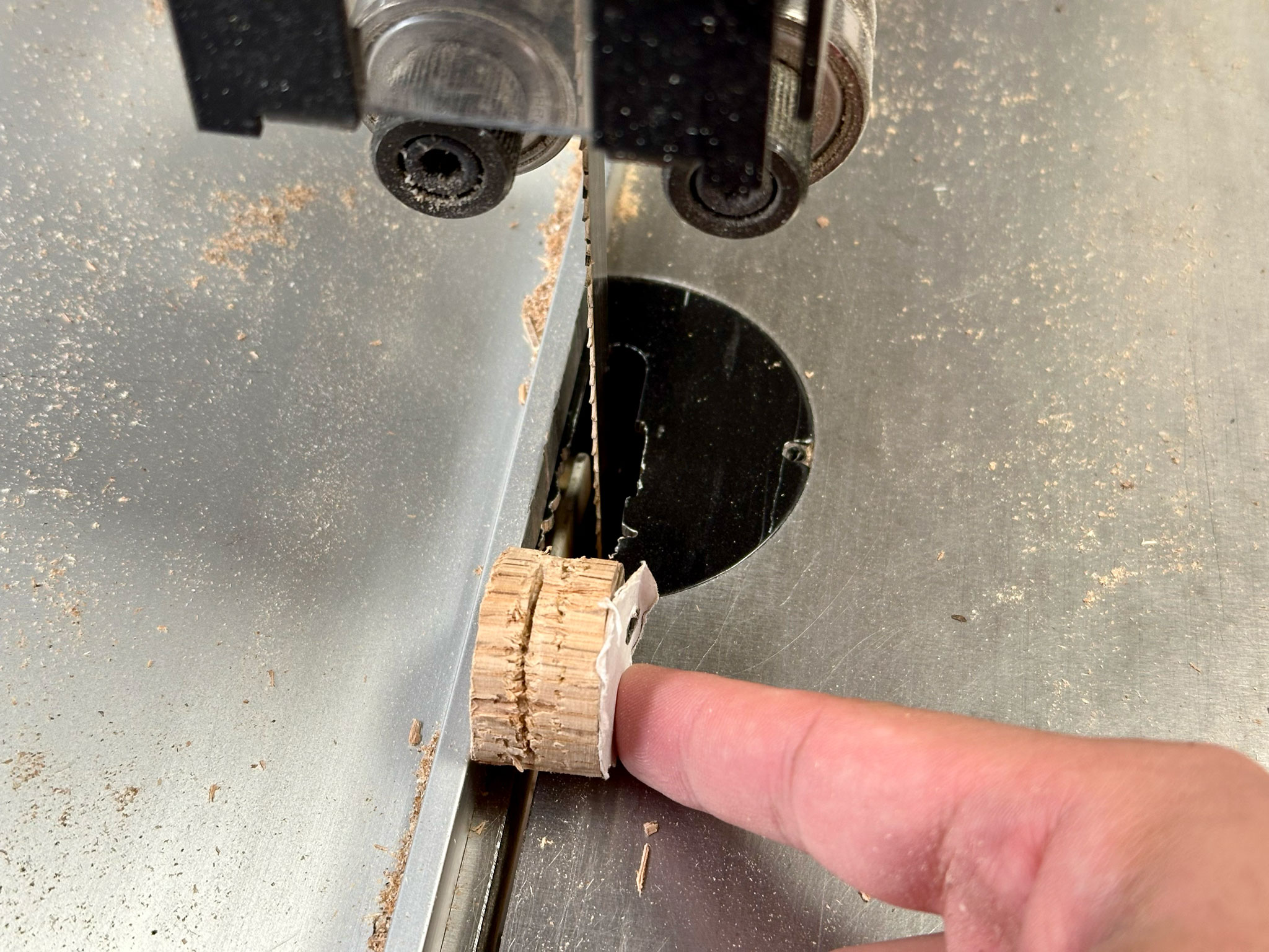
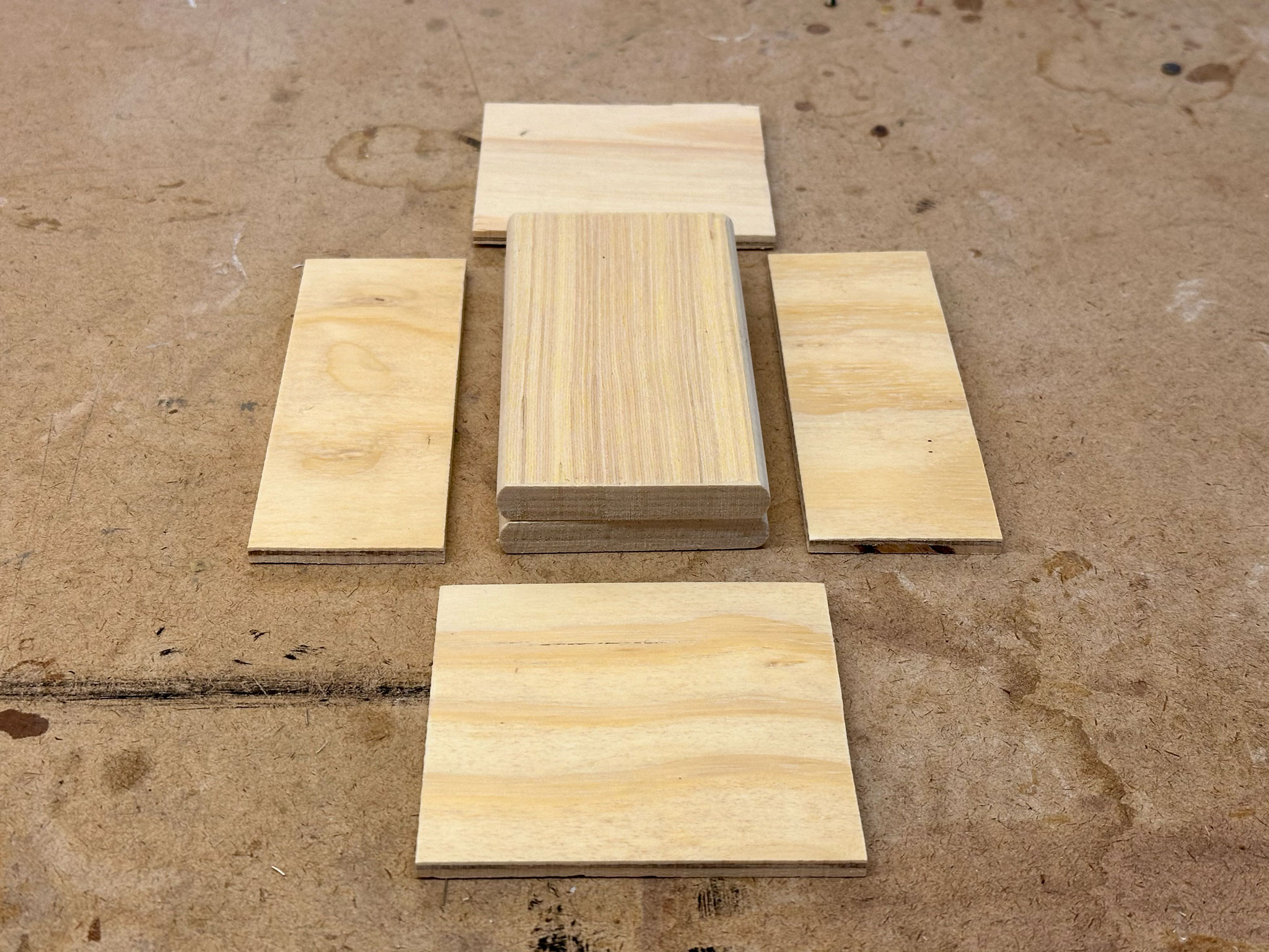
Once I shaped the wood block as even as I could, I moved back to the band saw to slice the block into even flat cam pieces by consistently pushing it against the fence.
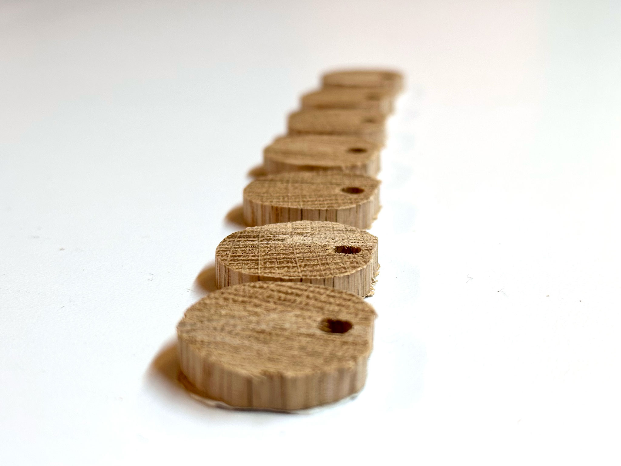
After slicing 7 pieces, the rest was too small to be sliced. I was still pretty happy with what I was able to get out of this wood block.
 |
 |
After some rough measurements and calculations, I was able to find a good piece of scrap plywood to make a structure to hold the whole mechanism.
I also found two pieces of wood panel that I was going to stack together to be the top side of the structure.
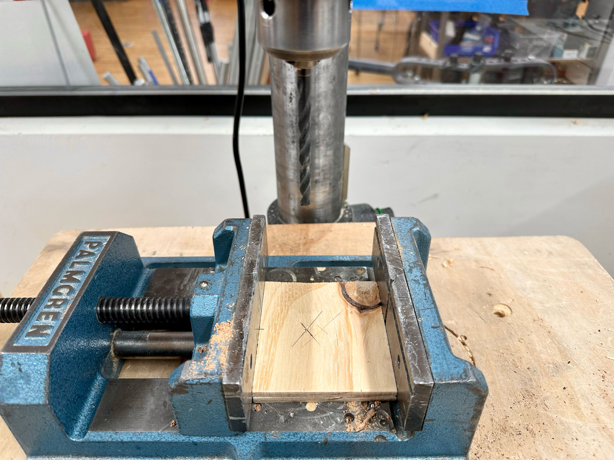
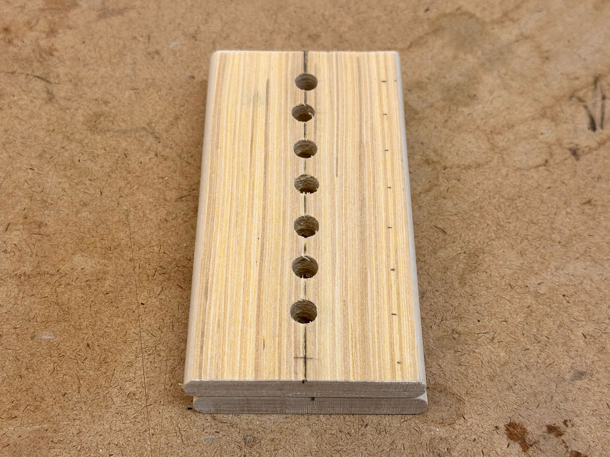
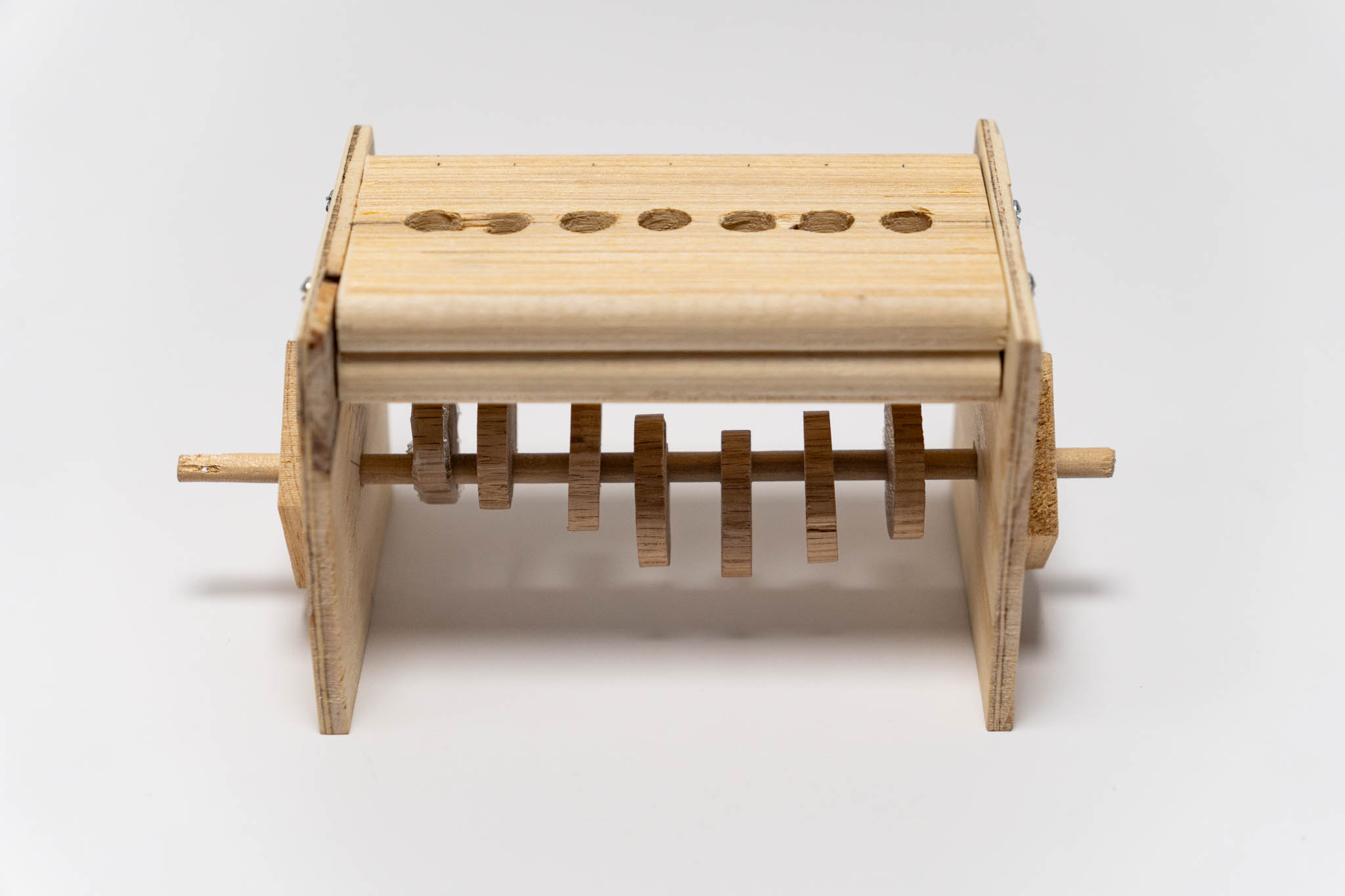
After some more measurements, I marked the points where holes needed to be drilled.
 |
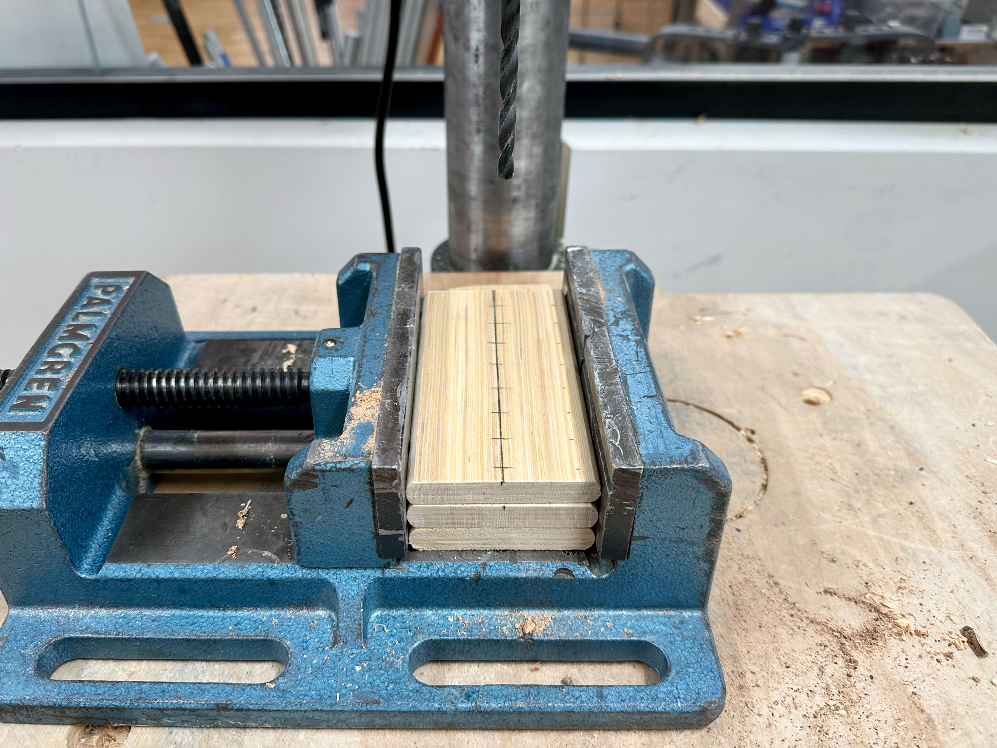 |
Without a jig, the holes were a bit uneven, but I was hopeful that it would still work.
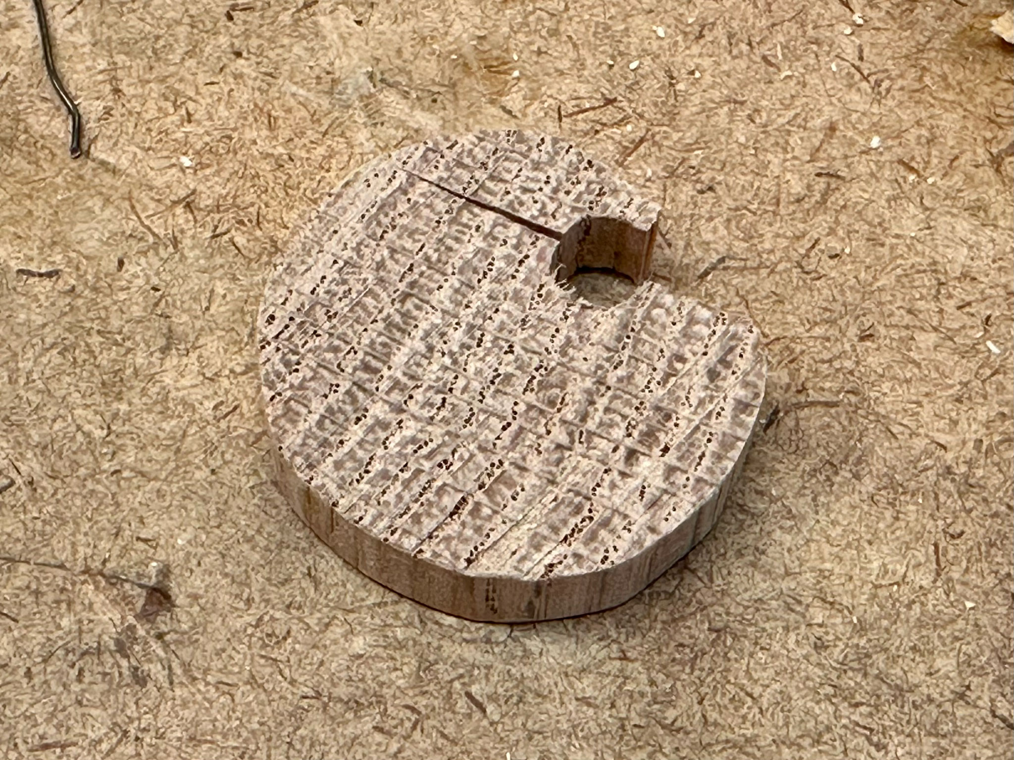
After all components were cut and drilled, I used some sand paper to smoothen all the sharp edges. It was finally time to assemble! As I attempted to install the first cam onto a wooden rod, the cam cracked. I believe it was its small size that made it very delicate. Since I did not have many cams, I did not want to lose a single one of them. Surprisingly, wrapping it with Scotch tape helped to keep it together. For all the other cam pieces, I used a hand file to make the holes slightly bigger to fit the wooden rod.
All pieces were finally assembled.
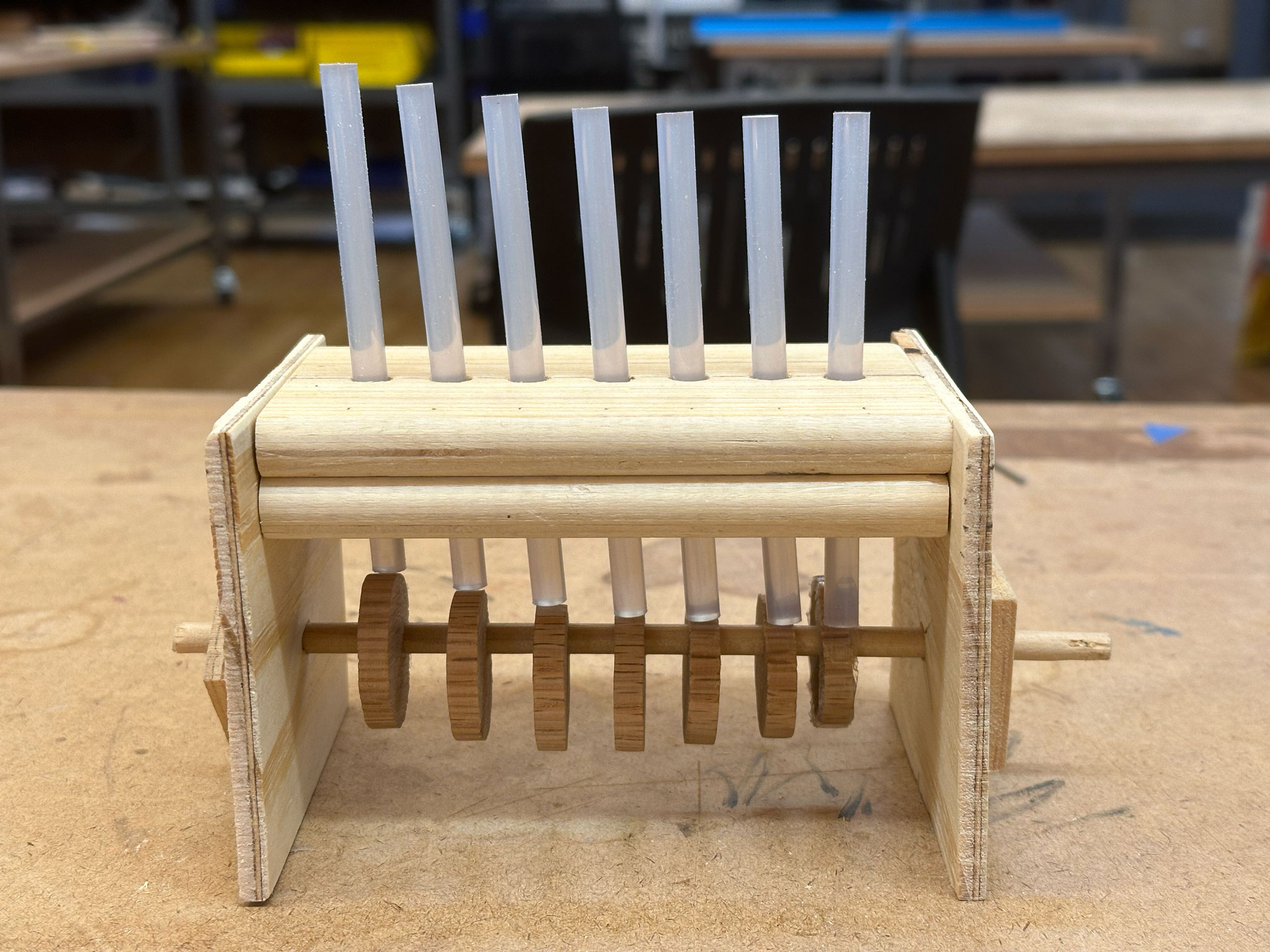
I quickly realized the glue sticks were too soft and kept getting caught by the cams. I had to switch to the pencils again, but the holes were designed for the glue sticks. I partially disassembled the structure and redrilled the holes with a hand drill to make them a bit bigger. I also used a Dremel to clean up the holes for a even smoother surface.
 |
 |
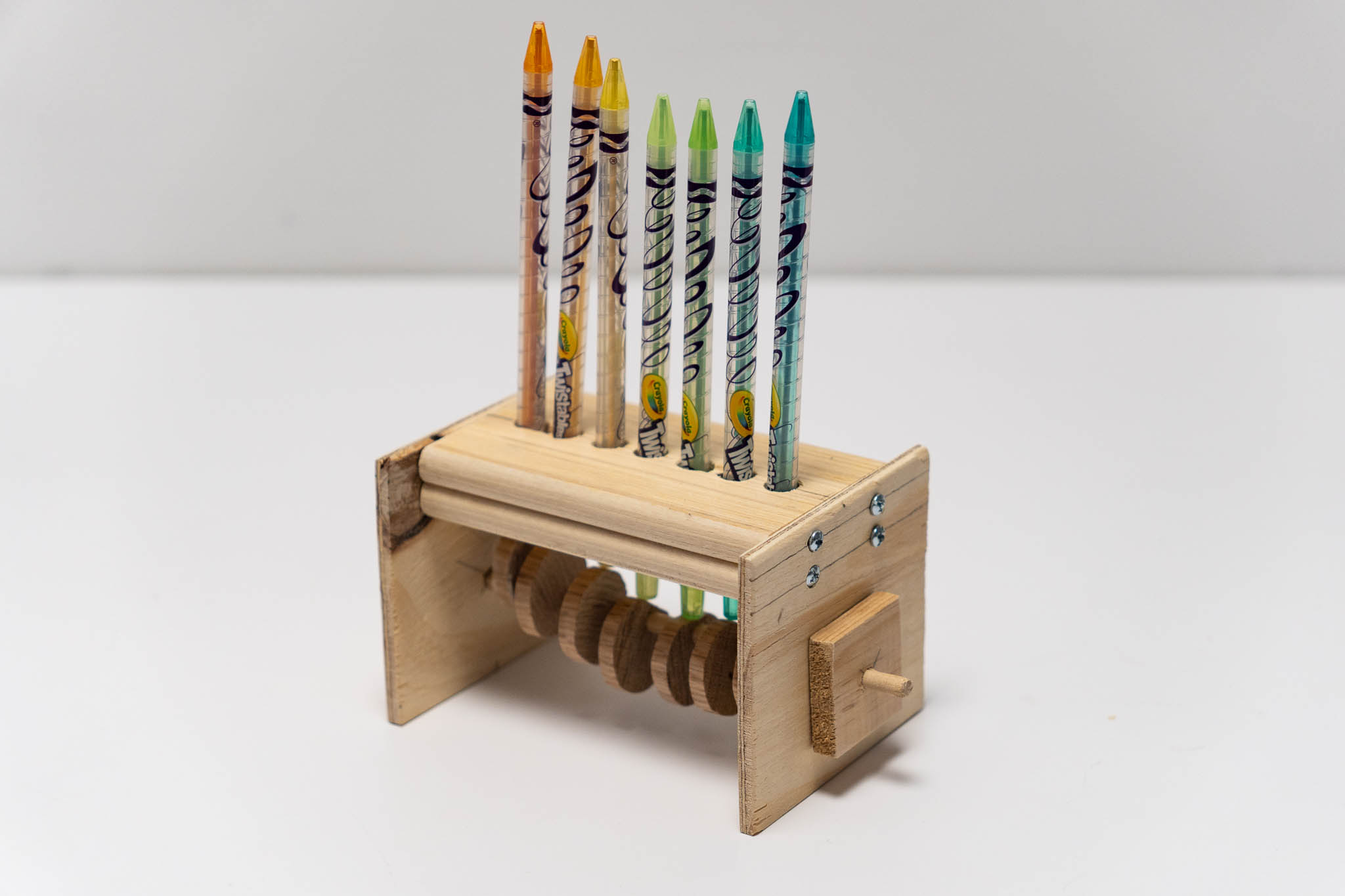
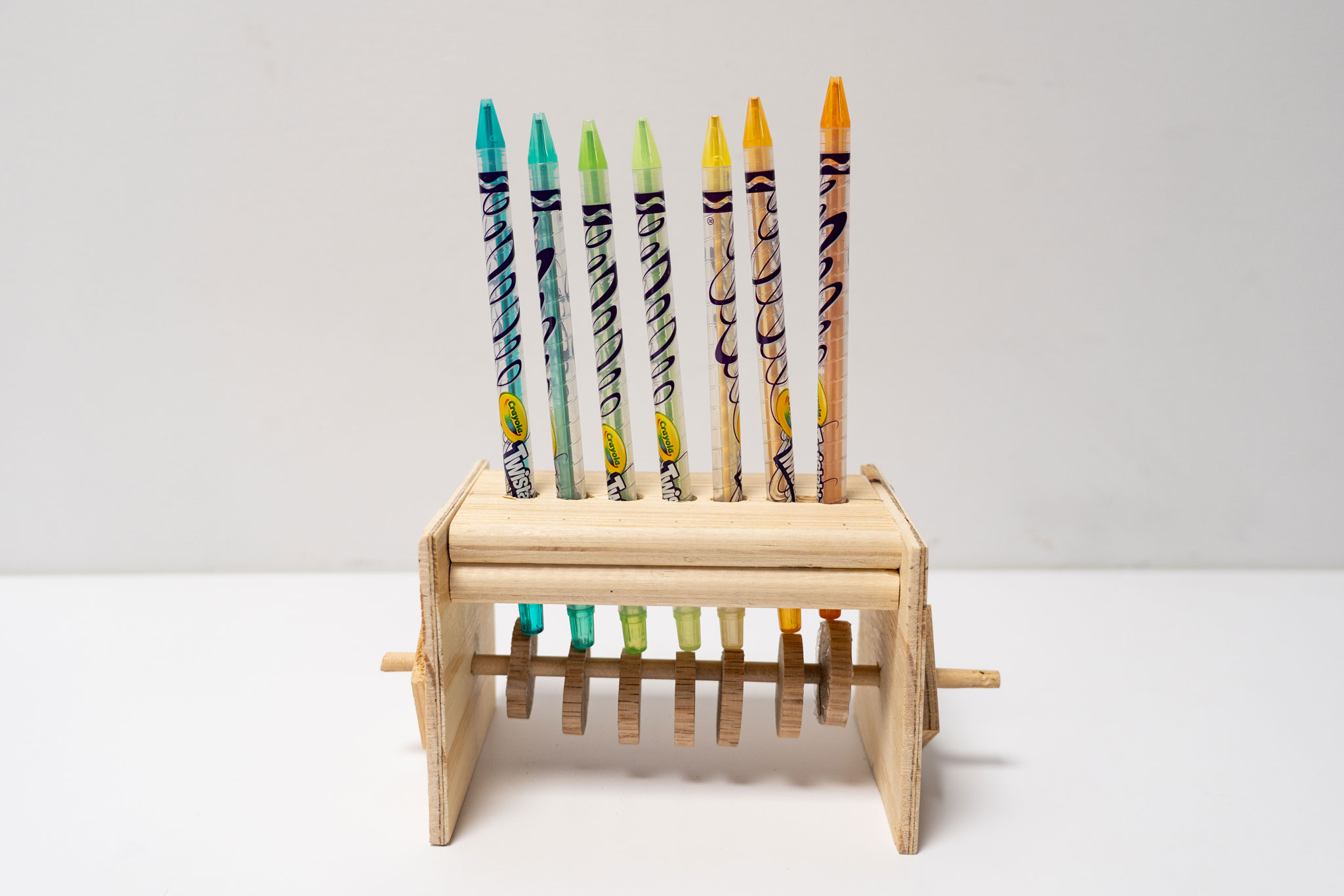
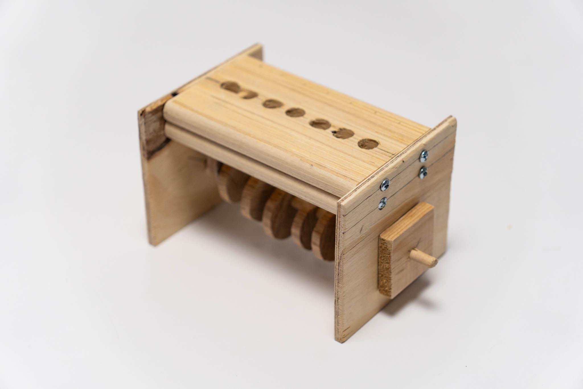
It finally worked!!!
Here are a couple of things I need to improve next time:
-
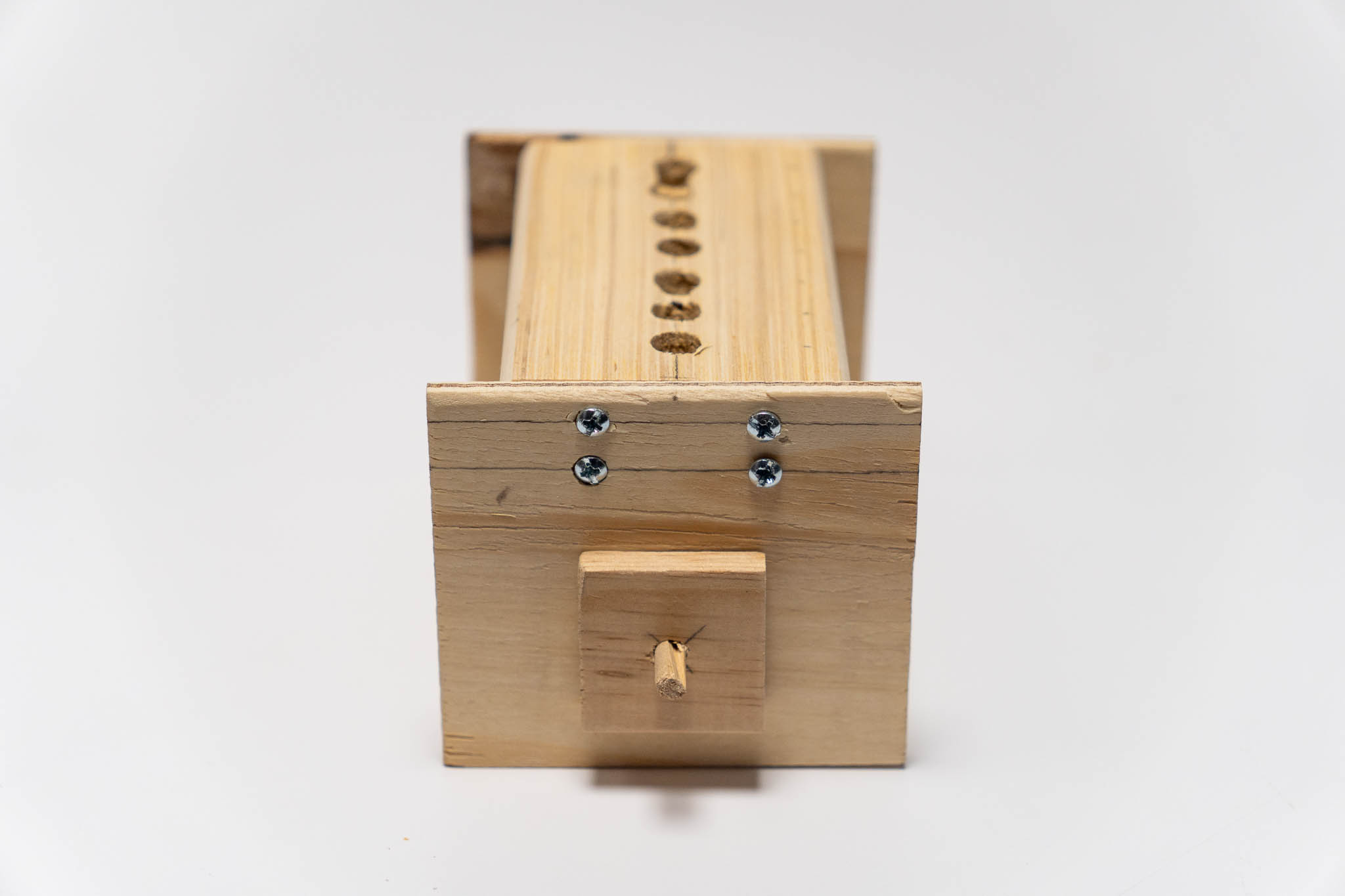
I should use the drill press for cleaner and smoother holes to minimize wobbling.
-
One other thing that can help reduce wobbling is to either increase the distance between the two top panels, or use a single piece of wood that is much thicker.
-
The cams should be installed on the rod with stronger frictions or completely glued together to avoid slipping.