Drawing Robot Redesigned #drawing #robot #mechanical #chaotic #scribble #pixelation #analog #fabrication #arduino #network #itp #prototyping-electronic-devices
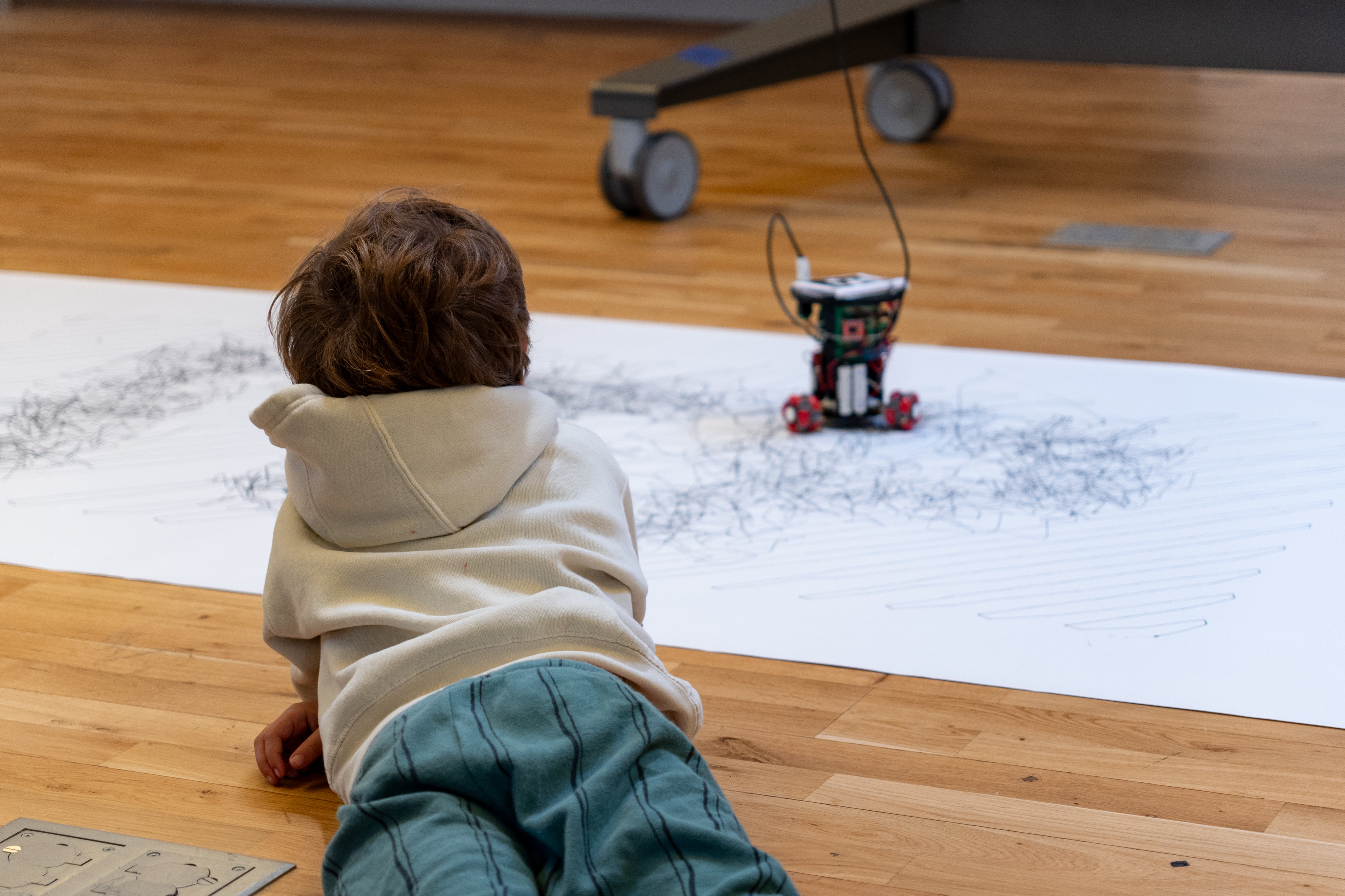
Back in 2017, I built my first mobile drawing robot for my undergraduate capstone at NYU Shanghai. Some of my design choices at the time were constrained by the resources and timeline. Now that I am back in school, pursing my master’s degree, I wanted to redesign the robot. My main goal was to make the robot smaller so it becomes more portable. I also thought this would be a nice challenge to practice my CAD skills and deepen my understanding of the electronics.
 |
|---|
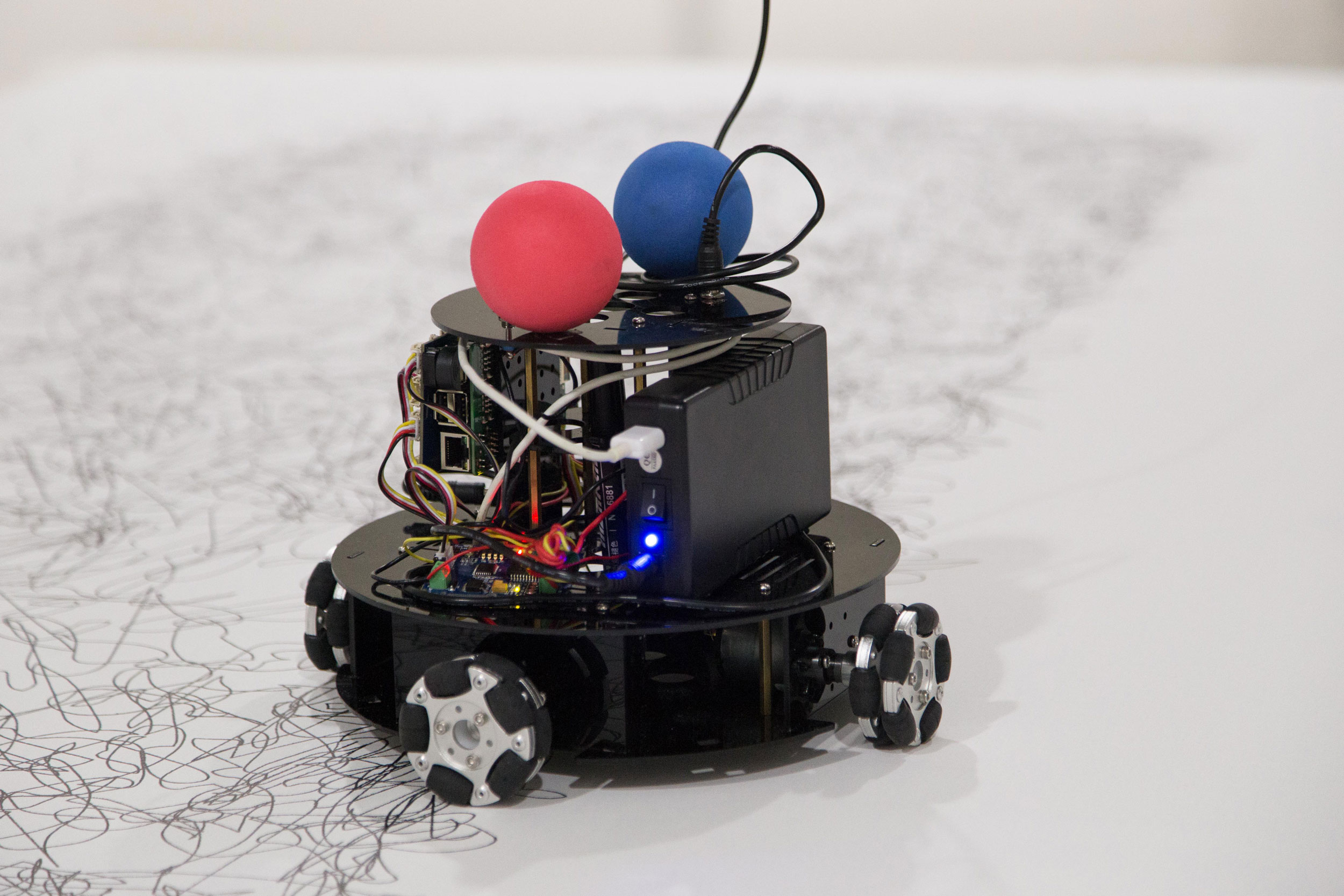
| Drawing Robot “Minus E” Developed in 2017 |
The original robot was constructed with laser cut acrylic chassis, partially for its flexibility. I designed general-purpose mounting holes on the chassis for a variety of potential components to be included. Since I already had a working robot as a reference, it became much easier to design a compact chassis that only incorporate the necessary components: DC motors, motor drivers, a micro controller, and some structure for holding the drawing instrument. The robot itself could easily be thought of as a general-purpose remote-controlled robot. The true magic lies in the computer that tracks where the robot is and send commands to it wirelessly.
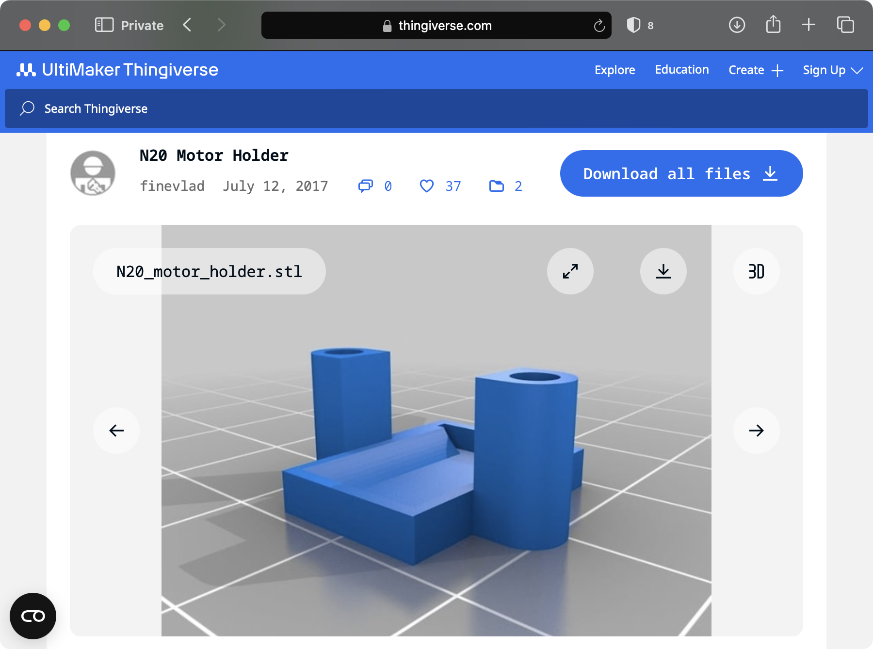
I did some research on different motor types and landed on N20 motors, which is a popular micro geared DC motor. It was so common that I was able to find 3D printable mounting brackets for it on Thingiverse, which saved me some time.
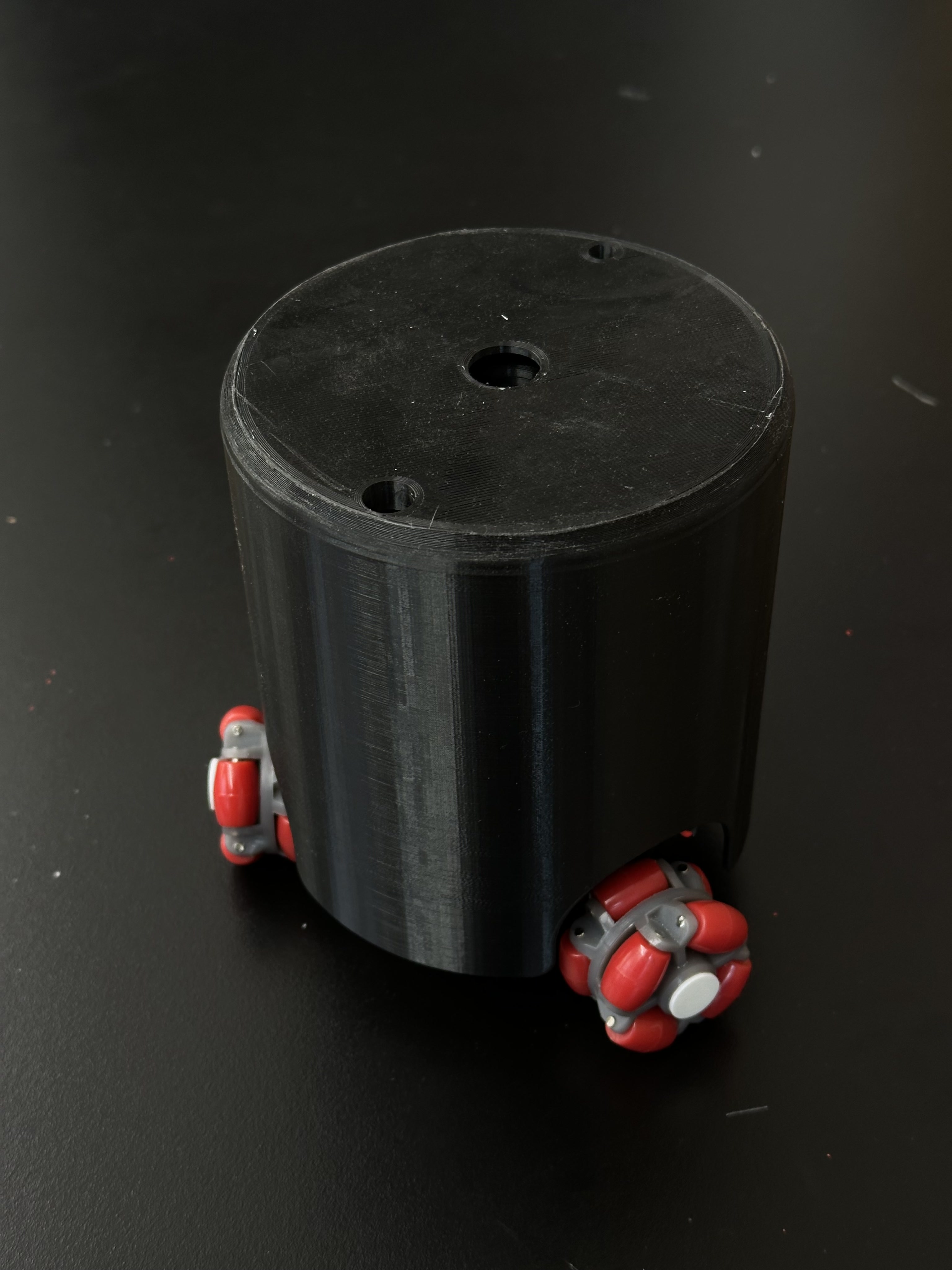
Once I decided on the type of motor I was going to use, I designed a barebone chassis in AutoDesk Fusion.
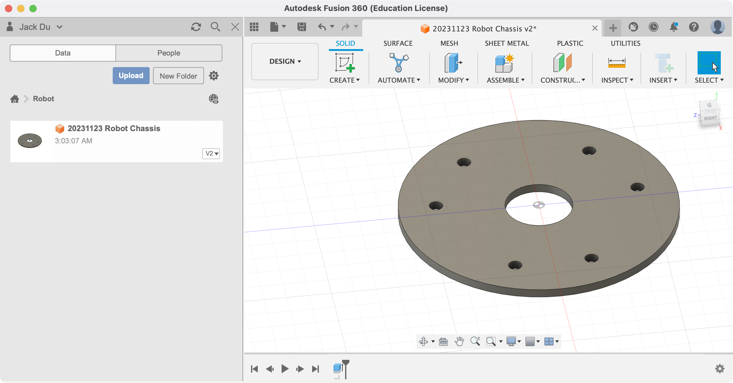
In particular, I moved from a four-wheel design to a three-wheel one. This alone helped reduce the size signicantly while also improving the stability and efficiency. I made sure to include a hole at the center for holding drawing instrument later.
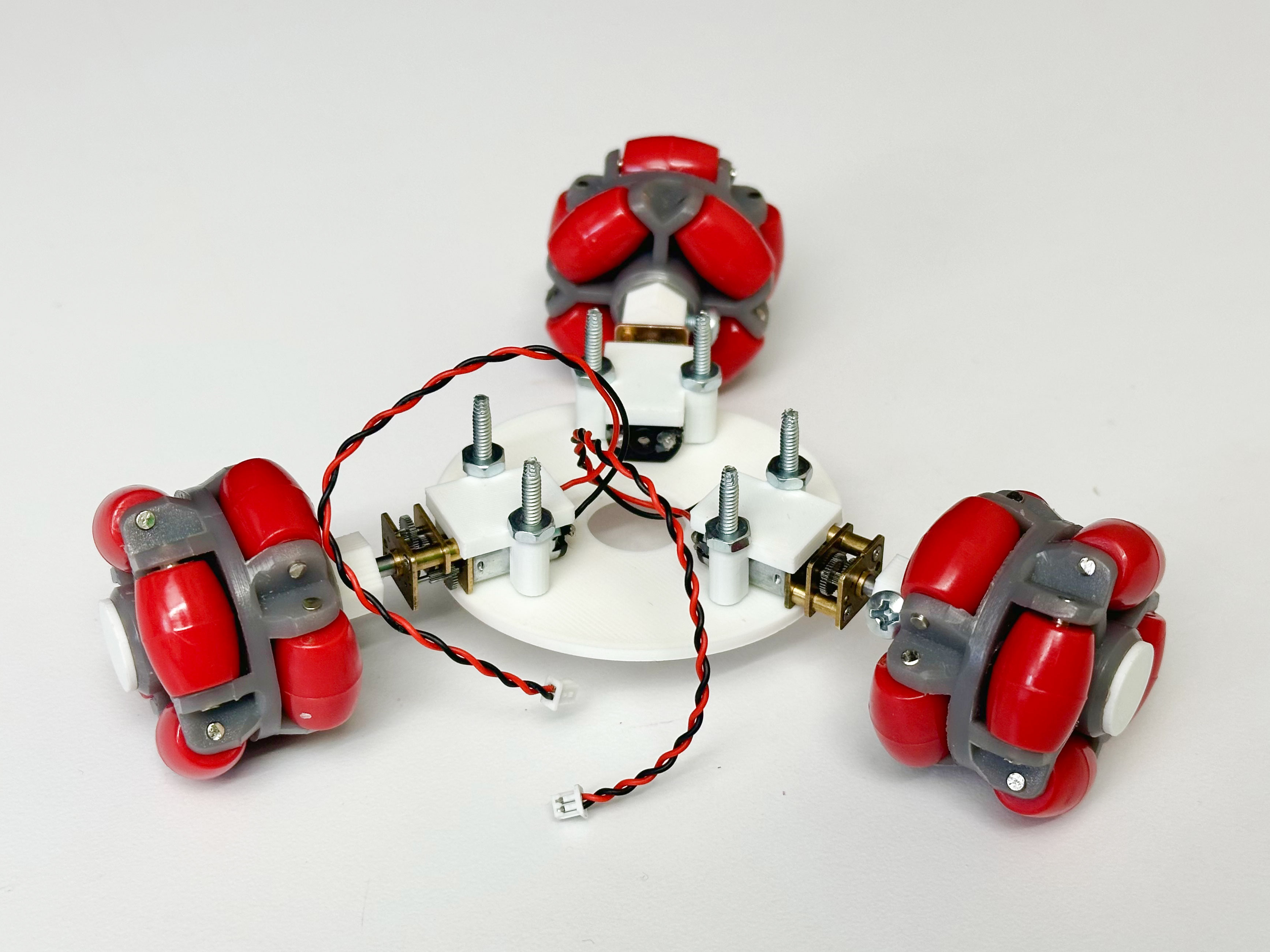
With this prototype, one key thing I was able to conclude was that three N20 motors have enough torque to move the robot around. I was initially a bit concerned as omni-wheels tended to be slippery, offering much less grip than a traditional rubber wheel.
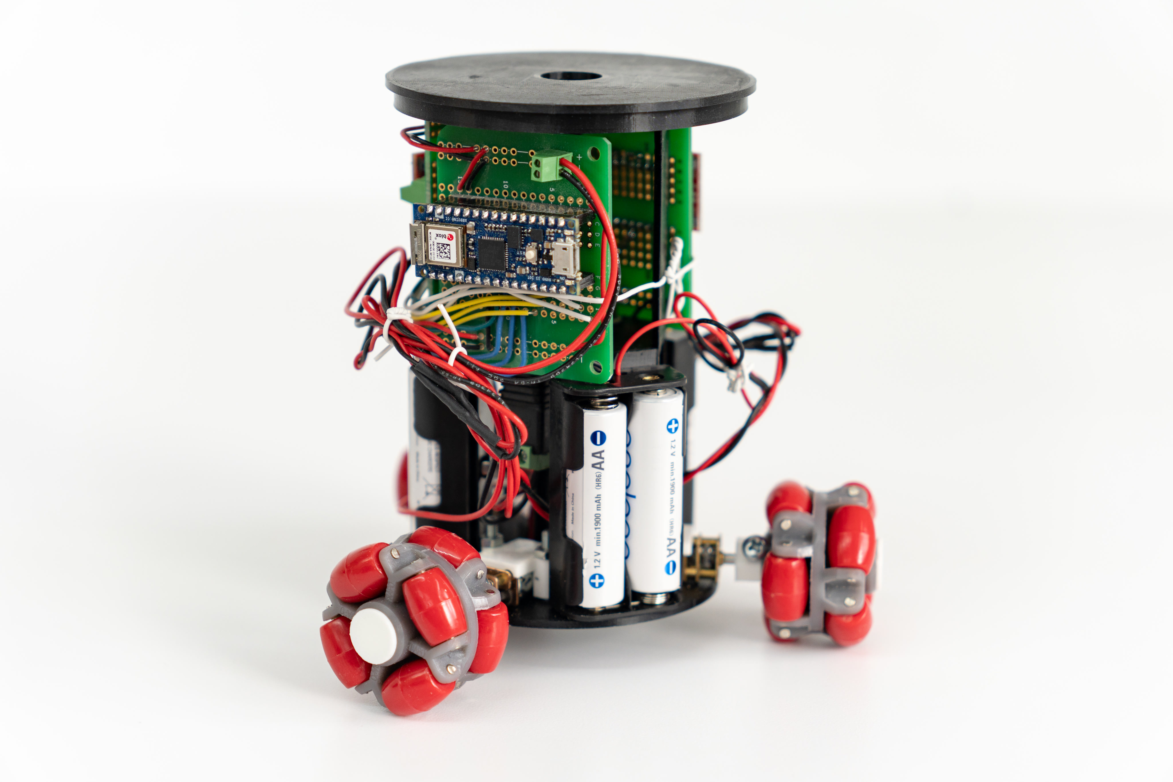
I continued this symmetrical design upwards by adding mounting holes for three dual-AA-battery holders. With 6 rechargeable lithium-ion AA batteries, the robot has about 7.8 volts, which was more than enough for Arduino Nano 33 IoT, the microcontroller I chose for the robot. I went on to source N20 motors rated for 6–12V so that 7.8V was within its range. After a series of tests, I was happy to find that these batteries provide enough power for three motors.
Still, for long drawing sessions, I was afraid the batteries would not last long enough to complete a drawing. That was why I included a barrel jack on the top of the chassis for power source, which could be connected to either the AA batteries or an external power supply. Using an external power supply could also mean more speed and torque, as it could go as high as 12 volts.
In order to mount the microcontroller and the motor drivers, I simply add one more level to the chassis to accomodate that. That also helped extend the center hole that holds the drawing instrument, which was much needed.
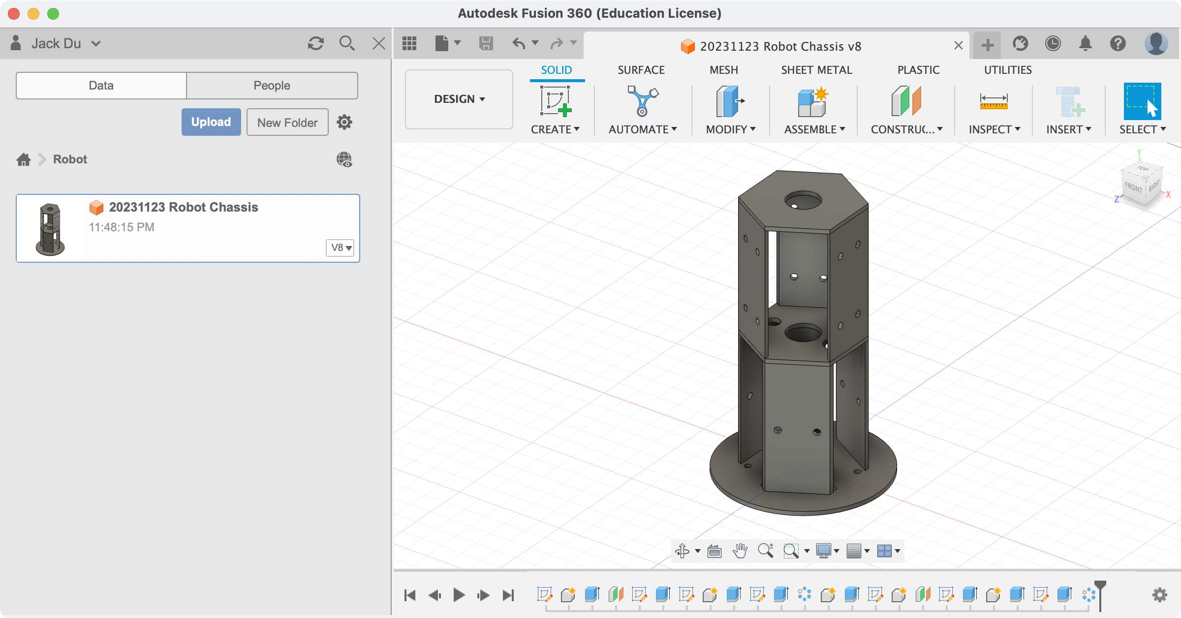
With one last hole one the top surface for a power switch, the design of the chassis was pretty much done.
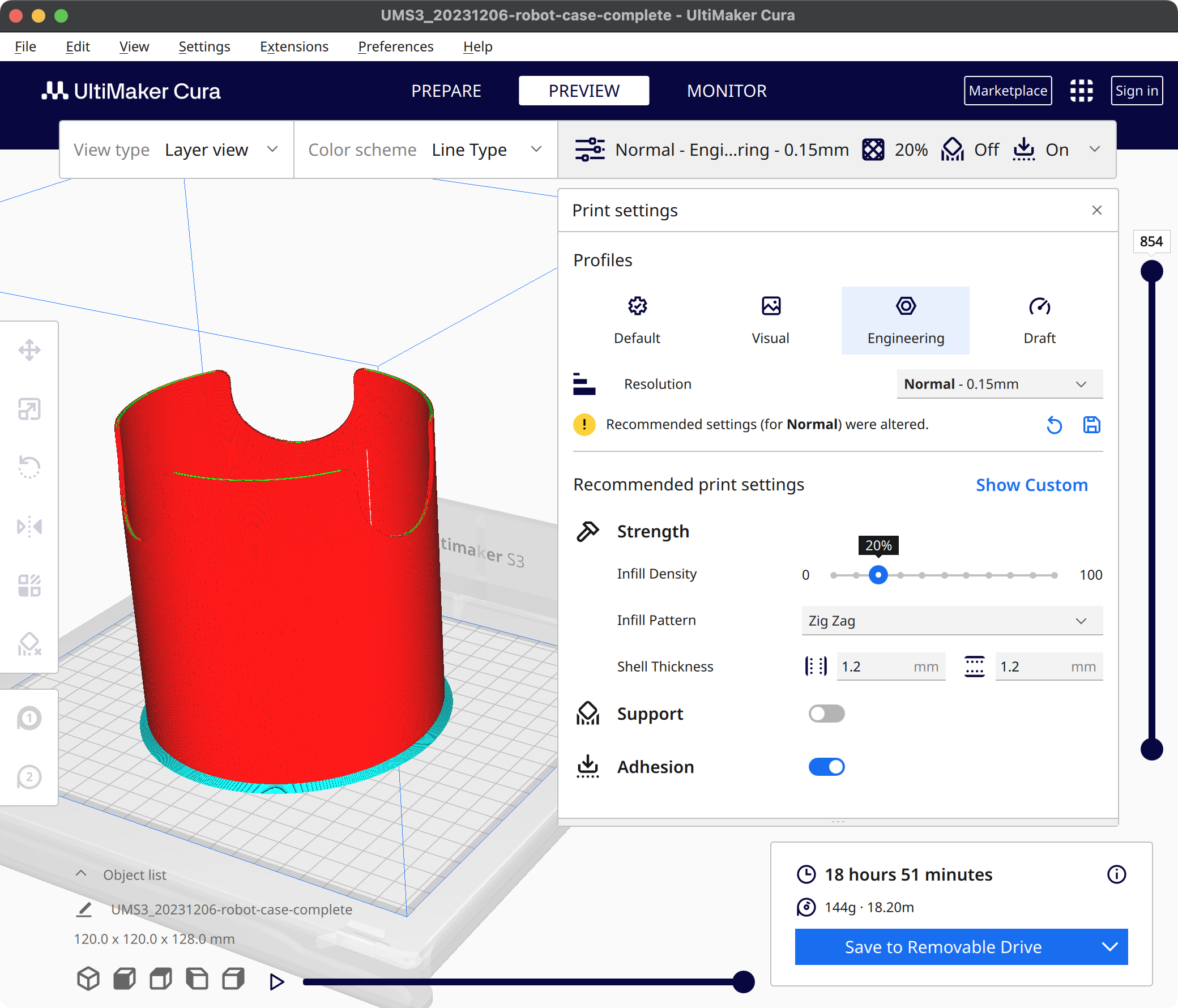
I tried adding a cylindrical enclosure for the entire robot, but I ended up not liking the “trash-can”-like look. I found the robot to be a lot more interesting to look at when its electronics were exposed.
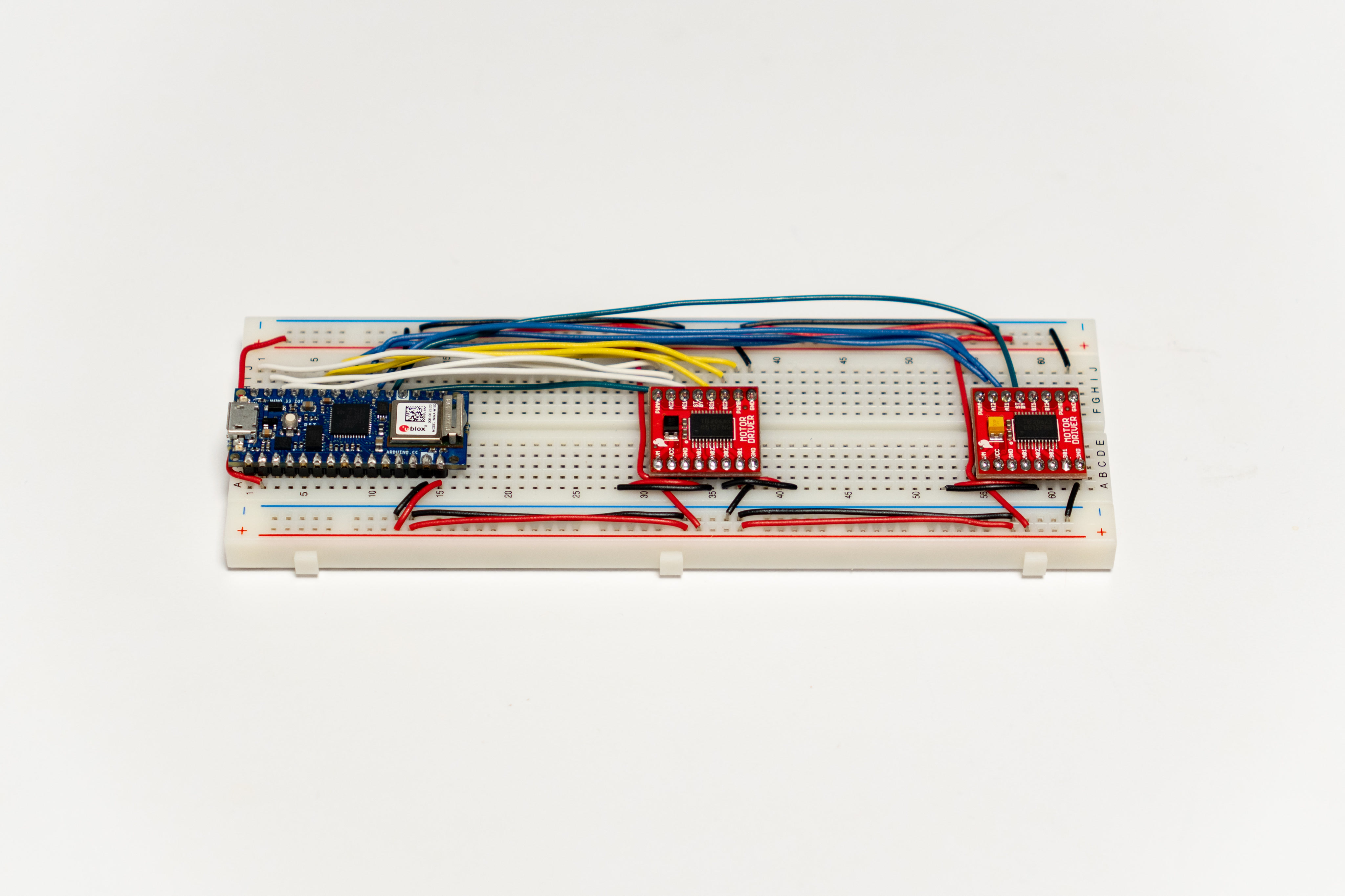
Once the whole circuit was tested on a breadboard, I moved everything to a protoboard and soldered them.
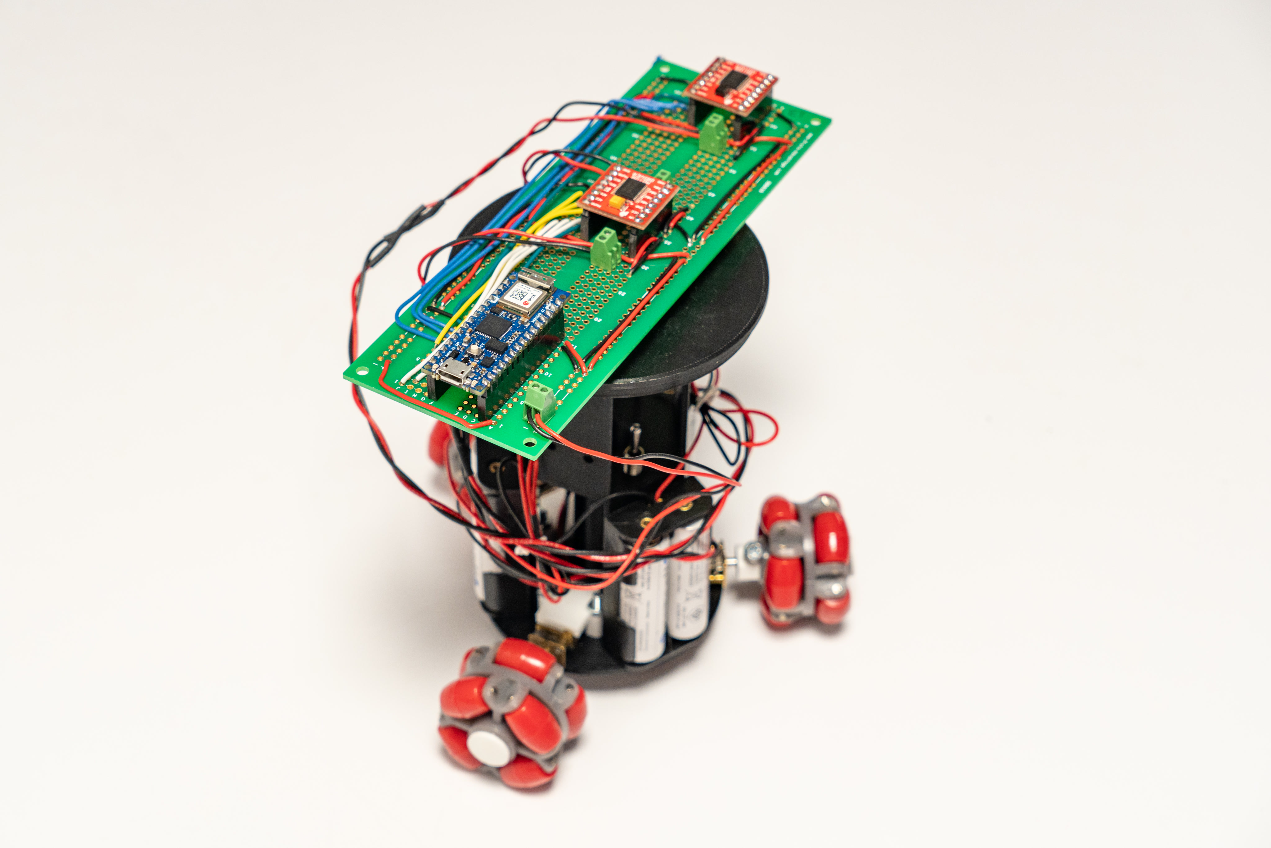
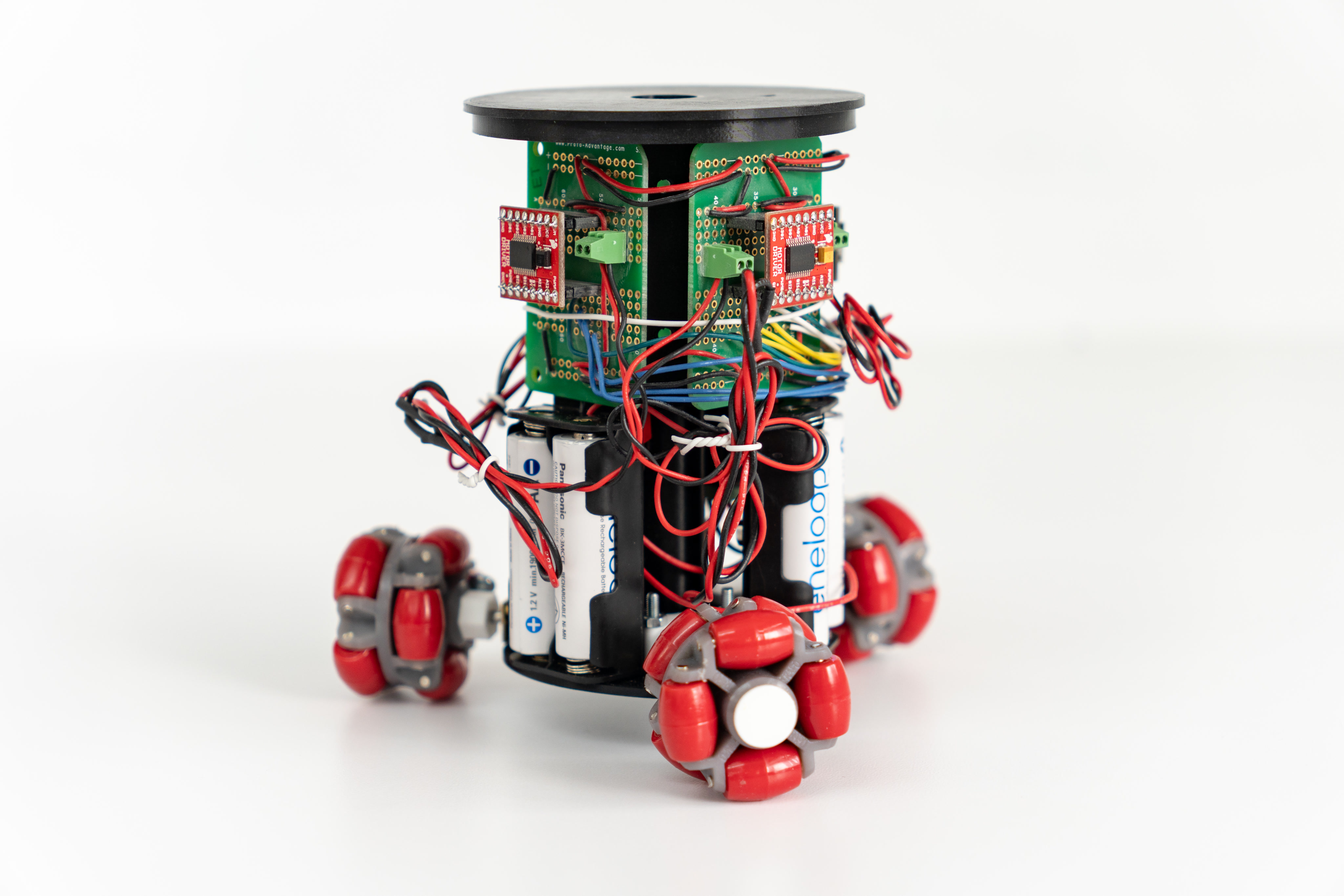
The protoboard was then broken up into three pieces so it could be wrapped around the robot chassis. The wires endend up being a little bit too tight. In a future version, I would probably switch the solid-core wires to longer stranded-core wires.
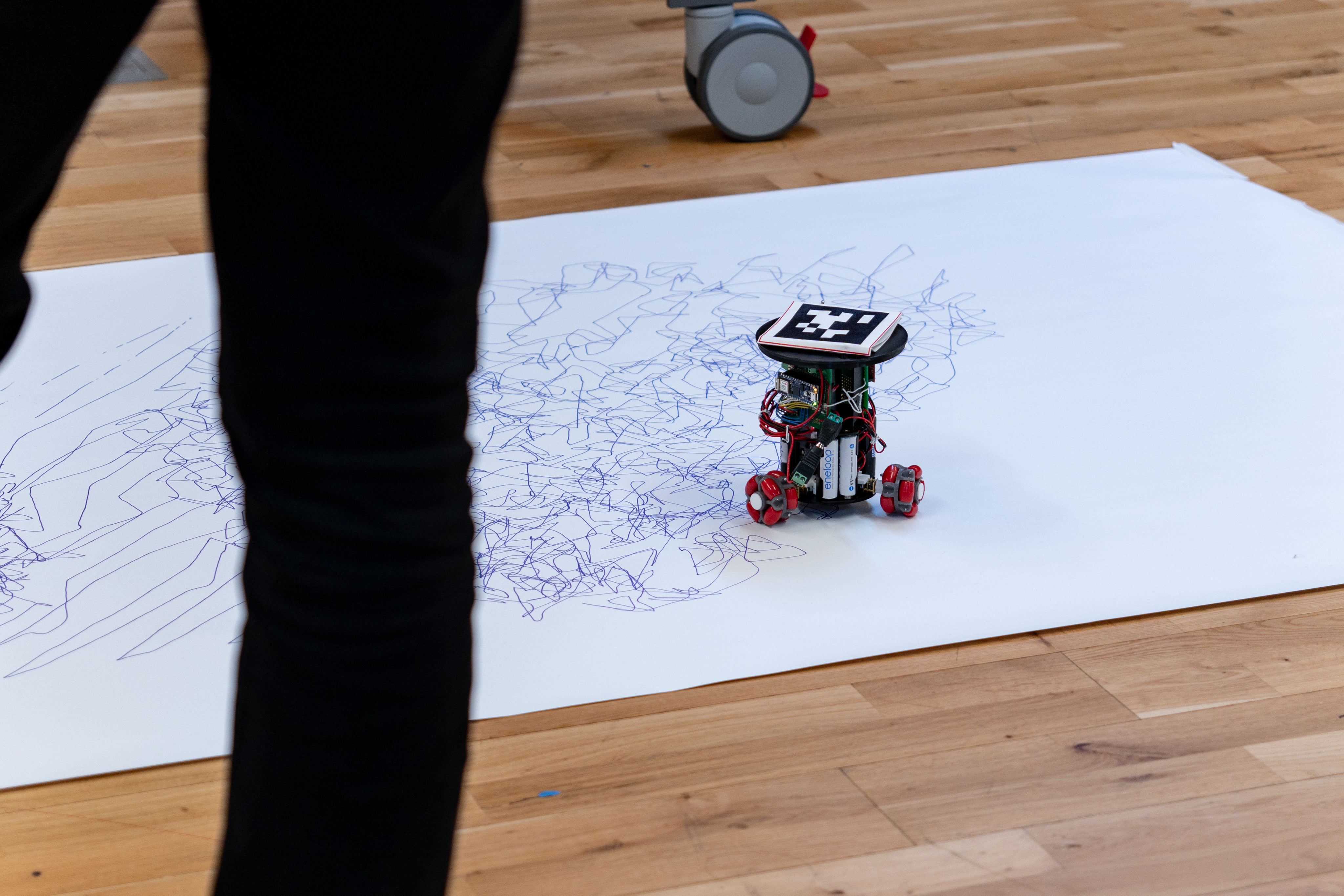
Viola! The robot was fully assembled! A general-purpose three-wheeled robot was completed. What was missing was the software.
On the microcontroller side, it was fairly simple. The microcontroller only needed to receive three values each representing the speed and direction of a motor. On the computer side, it was a bit more complicated. The original desktop controller program was written in python, using OpenCV for tracking. I wanted to rewrite it in JavaScript so that the controller program requires no setup. That way, it may even run on mobile devices.
One of the essnetial feature of the controller program was to track the robot’s position and orientation. In order to do that, the control system included a camera facing downwards from the ceiling and the entire drawing area must be within the camera’s field of view. For the original robot, I was using openCV’s color tracking feature to track two foam balls of different colors fixed on the robot. After numerous exhibitions, I found color tracking to be a bit too unreliable. It often required constant recalibration especially under unstable lighting conditions. To help tackle this issue, Deqing Sun, my professor for the Prototyping Electronic Devices class, recommended AprilTags. Luckily, I found a JavaScript library for AprilTag tracking. The code example for the library was using vanilla Canvas API for graphics, but I decided to use p5.js because its drawing API was a lot more convenient. Not to mention that the p5.Vector would also be extremely helpful for calculating desired motor speeds.
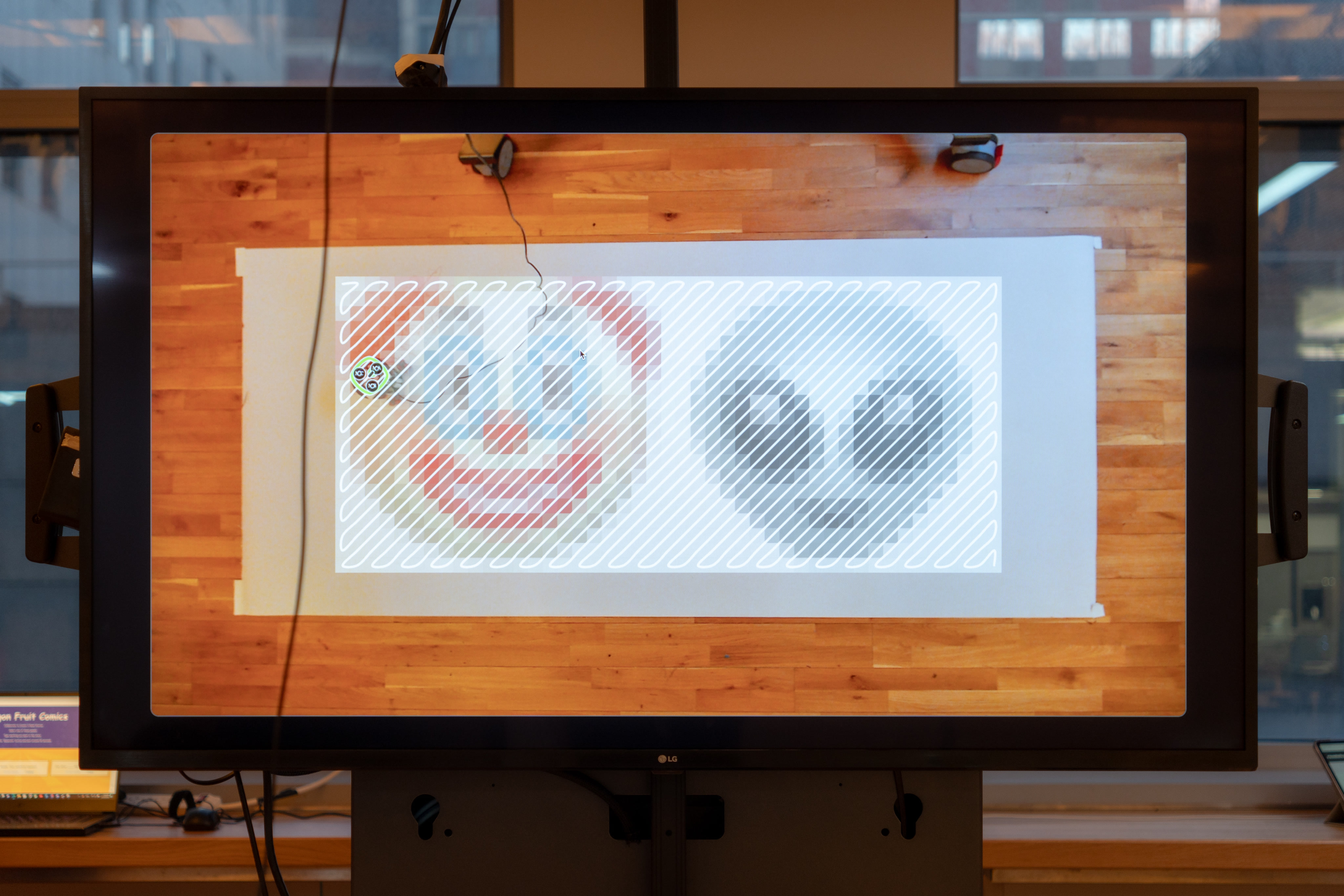
It took quite a while for me to get the AprilTag library to work with p5.js, but I was so glad I did. With the coordinate and orientation of the AprilTag obtained, I was able to draw a virtual version of the robot with unique labels for each motor. This was immensely helpful as I worked on the rest of the program.
To test and debug the robot, I created a program in which I could click anywhere on the camera view, and the robot would be directed to move to that location.
Once everything was tested to be working, it was fairly easy to port my original algorithm to JavaScript. If you are interested in learning more about the drawing algorithm, please refer to the post of my original robot.
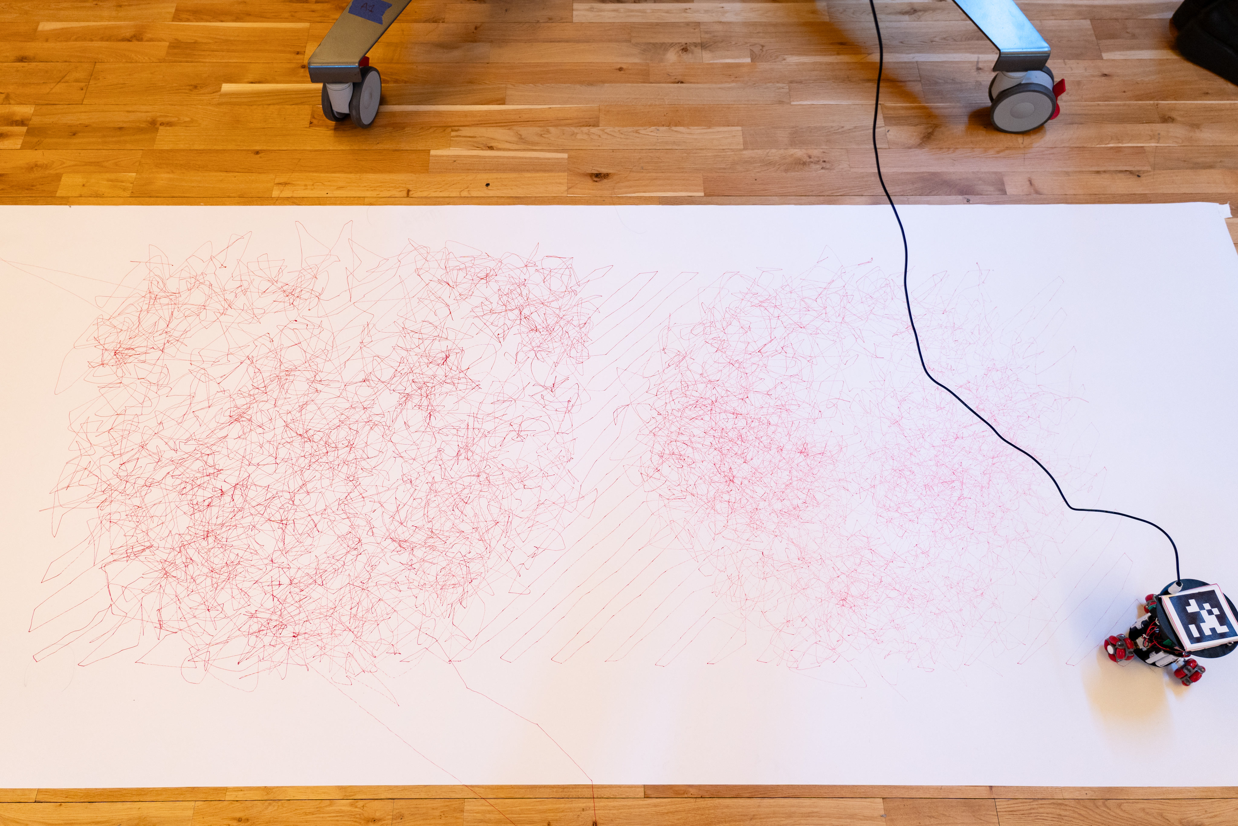
I even added new path to the algorithm so the robot could now traverse the pixels diagonally. I also added some UI element for choosing reference images. As soon as a reference image was selected, the controller program would process the image and send commands to the robot to perform the drawing.
 |
 |
